background image

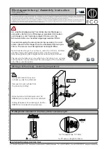
Figure 7: Lid Assembly 

To refit the Lid assembly;

1.

 Place Lid Assembly onto the Solenoid Switch enclosure.

Note: No additional sealing elements or compounds (for example Silicon sealant) are required to refit and reseal the 

Lid Assembly. Any additional materials or work may reduce IP level and will void Fortress warranty.

2.

 Refit and tighten the 10 x M8 Torx screws in an even distribution. For example;

i. Half tighten screws in the order specified in Figure 7.

ii. Fully tighten screws in the order specified in Figure 7.

iii. Check and, if necessary, re-tighten screws in the order specified in Fix.2. 

Note:


All M8 Torx lid screws must be fully refitted and tightened to a minimum torque setting of 20Nm to maintain IP 

level. Note: It is recommended that all M8 Torx Lid screws be secured against tampering removal or loosening due to 

vibration using a middle strength adhesive threadlocker. 

3.

 Fully test and operate the complete Alfred Solenoid Controlled Guard Lock to ensure correct function and operation. See  

    Mechanical Function Test section for more details.
If required, any replacement Lid assembly screws must be identical to those as supplied by Fortress and must be M8 x 

14mm, property class of A2-70 with a minimum yield strength of 700 MPa to ISO 3506, ISO 262, ISO 965-1, and ISO 965-3.

FORTRESS

A               company

Halma

www.fortressinterlocks.com

THE COPYRIGHT OF THIS DRAWING BELONGS TO FORTRESS INTERLOCKS Ltd. 

THE CONTENT OF THIS DRAWING IS CONFIDENTIAL AND MUST NOT BE 

DISCLOSED TO ANY 3rd PARTY WITHOUT SPECIFIC, WRITTEN APPROVAL.

ALL DIMENSIONS

ARE IN mm UNLESS

OTHERWISE STATED

A3

SCALE:

0.50

SHEET:

2 OF 3

ORIGINAL SIZE

DATE:

25-02-21

ISSUE:

0

ALFRED SAFETY SWITCH OPERATING INSTRUCTIONS IMAGES

DWG NO:

SD-00033

Operating Instructions: Alfred Solenoid Controlled Guard Lock

15

Electrical Connection and Installation
Tools and Fixings Required

Terminal Screwdriver.

Cable and Wiring selection requirements:

•  All cabling and wiring used to connect and install the Alfred Solenoid Controlled Guard Lock must be of an equal or greater 

level of ATEX and IECEx protection in order to maintain ATEX Device ratings (See ATEX, IECEx and HazLoc section for 

Device rating and detail).

•  Correctly rated and sized cable glands and connectors must be used in order to maintain the IP67 and IP69 protection 

rating of the Ex Rated Solenoid module.

Note: 

The conduit connection hole of the Solenoid Module is an M20 x 1.5mm pitch threaded hole.

•  The cable and cable gland used must have a minimum service temperature in excess of 70˚C.

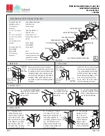
•  The wire used to connect to the Internal Earthing point of the Solenoid Module (see Figure 11) must have a greater than or 

equal cross-sectional area to that of the phase conductor wires.

Note: 

The internal Earthing point shall be used for the Equipment Grounding connection.

•  The wire or cabling used to connect to the External Earthing point of the Solenoid Module (see Figure 11) must have a 

cross-sectional area of at least 4mm2.

Note:

 The external Earthing point shall be used for a Supplementary Bonding Connection where local codes or authorities 

permit or require such connection.

•  Both the Internal and External Earthing wires must be secured and clamped so that they cannot be readily loosened or 

twisted. This could be done using a U-Shaped Saddle Clamp or similar.

•  All internal wiring for the Safety Circuits and Gate Monitor Circuits must be made using 24-16 AWG copper cable.

SWITCH ENCLOSURE

LID ASSEMBLY

M8 TORX LID SCREWS

Summary of Contents for EXPXL411

Page 1: ...operating instructions enclosed It must be installed by competent and qualified personnel who have read and understood the whole of this document prior to commencing installation If the equipment is u...

Page 2: ...65 3 4 When used for a Group III application the adhesive labels and non metallic coatings may store electrostatic charge and become a source of ignition Guidance on protection against the risk of ign...

Page 3: ...750mm Can be fitted in two positions at 90 to either hinged or sliding door gates Description Part No Handing Hinged Handle Assembly EXPHL1 Front Integrated handle for guarding applications with hinge...

Page 4: ...21 ALFRED SAFETY SWITCH OPERATING INSTRUCTIONS IMAGES DWG NO SD 00 2 LEFTHAND FACING DIRECTION OF ACTUATOR ENTRY 1 FRONT FACING HEAD 3 REAR FACING 4 RIGHTHAND FACING Head Modules Description Part No H...

Page 5: ...hinery that is required to be isolated before access Safety Key Adaptors Used to provide a personnel key function to prevent unexpected machine start up Extracted Key Adaptor Also used as a personnel...

Page 6: ...dard dustcover Description Part No Extracted Key Adaptor EKL7 Master lock type standard dustcover Description Part No Extracted Key Adaptor EKL3 Standard lock type padlockable dustcover Description Pa...

Page 7: ...olenoid EXPXL416 Power to Unlock device Dual Safety Circuits change state on opening closing of a guarded area or operation of an interlocked key Monitoring circuit on Solenoid action provides feedbac...

Page 8: ...channel Solenoid Voltage N A 24V DC 10 Solenoid Power Rating N A 350mA max 24V DC Solenoid Rating Duty Cycle N A 100 Transient Overvoltages Installation N A Category III Cable Size N A 28 12 AWG Diagn...

Page 9: ...depending on product selection and configuration See specific functioning section below With Solenoid de energised the Internal mechanism of the Power to Unlock Ex Rated Solenoid Module automatically...

Page 10: ...Monitor Circuit opens breaks Safety Circuits remain closed Gate Monitor Circuit remains broken Unlocking De Energise the Solenoid Internal locking mechanism dis engages to remove locking force from th...

Page 11: ...k product An Extracted style Key Adaptor will always be located closest to the Head Module If Extracted style and Safety style Key Adaptors are configured together their operation sequence will combin...

Page 12: ...essinterlocks com THE COPYRIGHT OF THIS DRAWING BELONGS TO FORTRESS INTERLOCKS Ltd THE CONTENT OF THIS DRAWING IS CONFIDENTIAL AND MUST NOT BE DISCLOSED TO ANY 3rd PARTY WITHOUT SPECIFIC WRITTEN APPRO...

Page 13: ...FORTRESS INTERLOCKS Ltd THE CONTENT OF THIS DRAWING IS CONFIDENTIAL AND MUST NOT BE DISCLOSED TO ANY 3rd PARTY WITHOUT SPECIFIC WRITTEN APPROVAL ALL DIMENSIONS ARE IN mm UNLESS OTHERWISE STATED A3 SC...

Page 14: ...ntenance procedures are all easily possible All fixing screws used to mount the complete Alfred Solenoid Controlled Guard Lock product must be permanently prevented from removal If mounting fixings ar...

Page 15: ...ATE 25 02 21 ISSUE 0 ALFRED SAFETY SWITCH OPERATING INSTRUCTIONS IMAGES DWG NO SD 00033 Operating Instructions Alfred Solenoid Controlled Guard Lock 15 Electrical Connection and Installation Tools and...

Page 16: ...Circuit and terminal 13 Solenoid Monitor Circuit Terminal 12 Guard Open Output Signal Control signal produced by the Ex Rated Solenoid Module to indicate that the Machine Guarding is in an open state...

Page 17: ...3 14 INTERNAL EARTHING POINT SHALL BE USED FOR EQUIPMENT GROUNDING CONNECTION FIX WITH M4 FIXING SCREW SUPPLIED SEE OPERATING INSTRUCTIONS FOR DETAILS XPXL471 13 3 4 EXTERNAL EARTHING POINT SHALL BE U...

Page 18: ...ard Lock product If damage or wear is found with an assembly please contact your local Fortress Channel Partner The complete interlock must be replaced after 1 million switching operations Disposal Th...

Page 19: ...the declaration described above is in conformity with the relevant Union harmonisation legislation 2014 34 EU The following harmonised standards and other technical specifications were used in suppor...

Page 20: ...e is in conformity with the relevant Union harmonisation legislation 2014 34 EU The following harmonised standards and other technical specifications were used in support of this declaration Harmonise...

Reviews: