
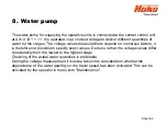
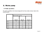


8. Water pump
8.2 Water pump standstill detection
Sheet 82
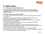
If the pump cannot delivery freely because the water cannot run freely
through the hoses to the brush, so-called water pump standstill detection
comes into effect.
Automatic water pump standstill detection:
The electronics offers the option to protect the water pump if the pump can no longer
convey freely.
This means: If the pump sucks water from the tank but cannot further convey
the water to the brushes, pressure builds up behind the pump.
Without protection from the electronics, the pump will now continue to pump against
this pressure and may be damaged.
The electronics detects that the pump cannot convey freely and automatically
switches the pump OFF for 2 seconds.
After these 2 seconds have expired, the pump is briefly switched back on while
simultaneously measuring whether the pump can now convey freely again or whether
the water supply to the brushes is still blocked.
If the pump can convey freely, it remains switched on in the selected stage.
If there is, however, still counter pressure, the pump is switched off again for 2 seconds.
This is repeated until the error has been eliminated.
Summary of Contents for Scrubmaster B175 R
Page 37: ...3 Technical Data Sheet 37...
Page 38: ...3 Technical Data Sheet 38...
Page 39: ...3 Technical Data Sheet 39...
Page 40: ...3 Technical Data Sheet 40...
Page 41: ...3 Technical Data Sheet 41...
Page 42: ...3 Technical Data Sheet 42...
Page 43: ...3 Technical Data Sheet 43...
Page 44: ...3 Technical Data Sheet 44...
Page 46: ...4 1 Hako System Maintenance customer Sheet 46...
Page 47: ...4 1 Hako System Maintenance customer Sheet 47...
Page 48: ...4 2 Hako System Maintenance I Sheet 48...
Page 49: ...4 2 Hako System Maintenance I Sheet 49...
Page 50: ...4 2 Hako System Maintenance I Sheet 50...
Page 51: ...4 3 Hako System Maintenance II Sheet 51...
Page 52: ...4 4 Hako System Maintenance III S Safety Check Sheet 52...
Page 65: ...6 Machine settings 6 1 6 Charging characteristics for integrated charger Sheet 65...
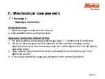
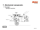
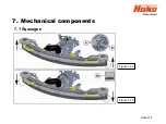
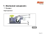
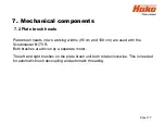
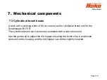
Page 74: ...7 Mechanical components Figure 7 2a Figure 7 2b Sheet 74 7 1 Squeegee...
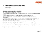
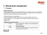
Page 76: ...7 Mechanical components Height adjustment Figure 7 4 Sheet 76 7 1 Squeegee...
Page 104: ...9 Drive 9 2 4 Steering angle sensor Figure 9 5 180 130 170 150 120 Folie 104...
Page 113: ...11 Battery charger 11 1 Operating manual Sheet 113...
Page 114: ...11 Battery charger Sheet 114 11 1 Operating manual...
Page 115: ...11 Battery charger Sheet 115 11 1 Operating manual...
Page 116: ...11 Battery charger Sheet 116 11 1 Operating manual...
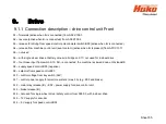
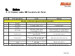
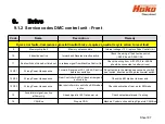
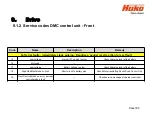
Page 123: ...13 Notes Sheet 123...
Page 124: ...Sheet 124 13 Notes...


