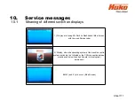
10. Service messages
Sheet 107
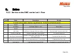
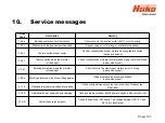
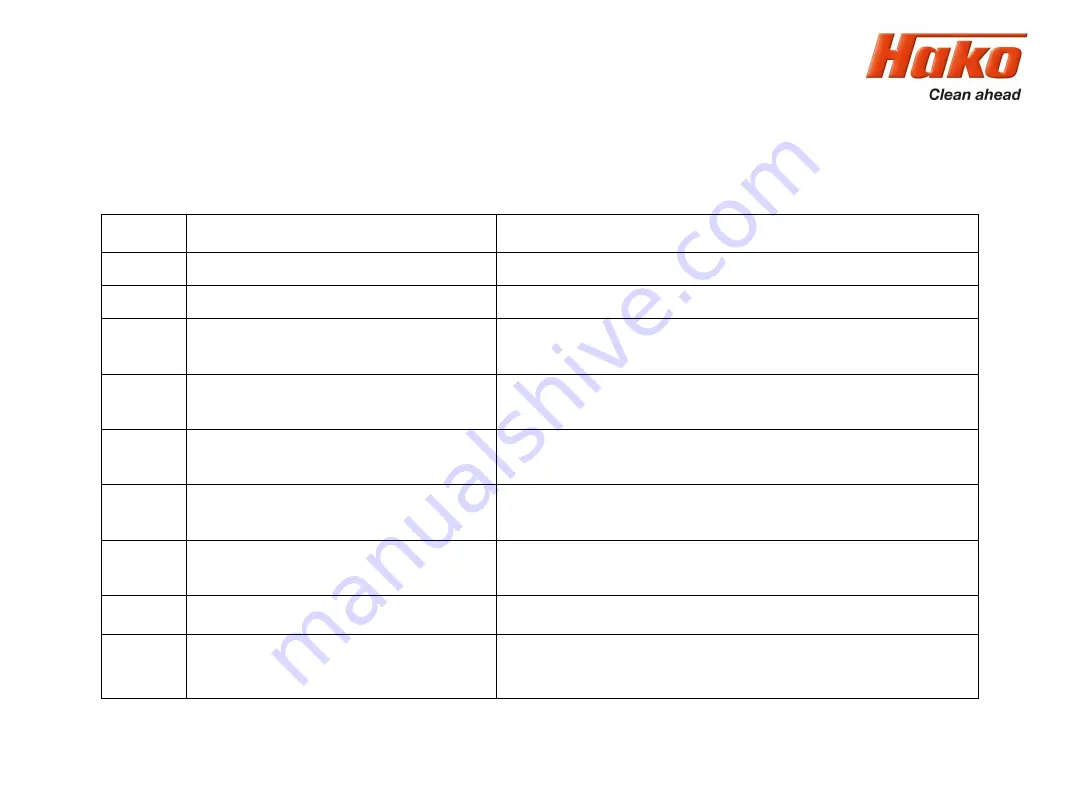
Service-
Code
Description
Remedy
1.4.6.4.
Blocking protection Suction motor 2
Short circuit in the suction motor (-M17) or in it´s wiring
1.5.5.1.
Malfunction Filling sensor solution tank
Sensor value out of it´s range; recalibrate the sensor
2.2.5.1.
Thermo switch broom motor
Current consumption broom motor and wiring thermo switch
(option pre sweep)
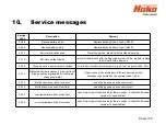
2.3.5.1.
Thermo switch side broom motor
left and right
Current consumption side broom motors and wiring thermo switches
(option side broom)
2.3.6.1
Blocking protection side broom motor
left and right
Short circuit in the side broom motors or in it´s wiring
(option side broom)
2.3.6.4.
Blocking protection side broom lifting element
Lifting element side broom overloaded
(option side broom)
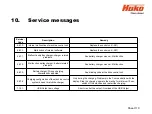
3.1.1.2.
Fleetrekorder communication interruption
Check wiring between machine control unit and Fleetrecorder
(CAN-Bus)
3.1.5.2.
Additional power supply during charging
During charging process; Invalid power supplly in Key switch circuit
3.1.6.E.
Power fuses (group signal)
Check fuses on the -A01 board, The voltage between -A01.X1 and -
A01.X2 is insufficient
Summary of Contents for Scrubmaster B175 R
Page 37: ...3 Technical Data Sheet 37...
Page 38: ...3 Technical Data Sheet 38...
Page 39: ...3 Technical Data Sheet 39...
Page 40: ...3 Technical Data Sheet 40...
Page 41: ...3 Technical Data Sheet 41...
Page 42: ...3 Technical Data Sheet 42...
Page 43: ...3 Technical Data Sheet 43...
Page 44: ...3 Technical Data Sheet 44...
Page 46: ...4 1 Hako System Maintenance customer Sheet 46...
Page 47: ...4 1 Hako System Maintenance customer Sheet 47...
Page 48: ...4 2 Hako System Maintenance I Sheet 48...
Page 49: ...4 2 Hako System Maintenance I Sheet 49...
Page 50: ...4 2 Hako System Maintenance I Sheet 50...
Page 51: ...4 3 Hako System Maintenance II Sheet 51...
Page 52: ...4 4 Hako System Maintenance III S Safety Check Sheet 52...
Page 65: ...6 Machine settings 6 1 6 Charging characteristics for integrated charger Sheet 65...
Page 74: ...7 Mechanical components Figure 7 2a Figure 7 2b Sheet 74 7 1 Squeegee...
Page 76: ...7 Mechanical components Height adjustment Figure 7 4 Sheet 76 7 1 Squeegee...
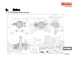
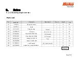
Page 104: ...9 Drive 9 2 4 Steering angle sensor Figure 9 5 180 130 170 150 120 Folie 104...
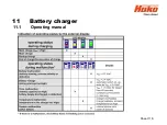
Page 113: ...11 Battery charger 11 1 Operating manual Sheet 113...
Page 114: ...11 Battery charger Sheet 114 11 1 Operating manual...
Page 115: ...11 Battery charger Sheet 115 11 1 Operating manual...
Page 116: ...11 Battery charger Sheet 116 11 1 Operating manual...
Page 123: ...13 Notes Sheet 123...
Page 124: ...Sheet 124 13 Notes...

