
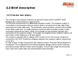


2.2.2 Solution tank display
2.2 Brief description
Sheet 16
The machine has a fill level indicator for the fresh water tank in the MFD which
displays the current fill level in steps of 20%.
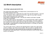
The fill level is measured via a differential pressure sensor. The pressure sensor is
connected to an immersion tube via a hose which is located next to the water filling
opening of the fresh water tank. The immersion tube extends to just above the bottom
of the fresh water tank. A certain pressure is present at the pressure sensor via the
immersion tube and the hoses, which is converted into an electrical signal by the
electronics of the pressure sensor. This signal is evaluated by the machine control unit
and shown on the display as a fill level signal.
The sensor is supplied with a voltage of 5V via A01:X14.5. The minus connection
comes from A01:X15.15,and the analogue signal of the pressure sensor is present at
A01:X15.3.
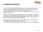
In case a water column is present in the immersion tube, the water filling indication is
misaligned. The recalibration of the filling indication display is done by the following
procedure: empty the fresh water tank complete. This will also empty the immersion
tube in the fresh water tank and recalibrate the filling indication.
Summary of Contents for Scrubmaster B175 R
Page 37: ...3 Technical Data Sheet 37...
Page 38: ...3 Technical Data Sheet 38...
Page 39: ...3 Technical Data Sheet 39...
Page 40: ...3 Technical Data Sheet 40...
Page 41: ...3 Technical Data Sheet 41...
Page 42: ...3 Technical Data Sheet 42...
Page 43: ...3 Technical Data Sheet 43...
Page 44: ...3 Technical Data Sheet 44...
Page 46: ...4 1 Hako System Maintenance customer Sheet 46...
Page 47: ...4 1 Hako System Maintenance customer Sheet 47...
Page 48: ...4 2 Hako System Maintenance I Sheet 48...
Page 49: ...4 2 Hako System Maintenance I Sheet 49...
Page 50: ...4 2 Hako System Maintenance I Sheet 50...
Page 51: ...4 3 Hako System Maintenance II Sheet 51...
Page 52: ...4 4 Hako System Maintenance III S Safety Check Sheet 52...
Page 65: ...6 Machine settings 6 1 6 Charging characteristics for integrated charger Sheet 65...
Page 74: ...7 Mechanical components Figure 7 2a Figure 7 2b Sheet 74 7 1 Squeegee...
Page 76: ...7 Mechanical components Height adjustment Figure 7 4 Sheet 76 7 1 Squeegee...
Page 104: ...9 Drive 9 2 4 Steering angle sensor Figure 9 5 180 130 170 150 120 Folie 104...
Page 113: ...11 Battery charger 11 1 Operating manual Sheet 113...
Page 114: ...11 Battery charger Sheet 114 11 1 Operating manual...
Page 115: ...11 Battery charger Sheet 115 11 1 Operating manual...
Page 116: ...11 Battery charger Sheet 116 11 1 Operating manual...
Page 123: ...13 Notes Sheet 123...
Page 124: ...Sheet 124 13 Notes...


