HAKARU PLUS TFL-B101Q Manual Download Page 2

HAKARU PLUS CORPORATION Tel. 81-6-6300-2195 

Page 2

05/12/16   TFL-B101Q DS (FL6)

Controls and Indicators
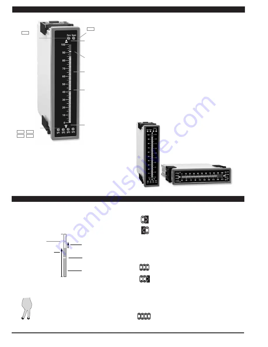
101 Segment Bar

Setpoint indicated 

by an OFF Segment 

UP Button Indicator

DOWN Button 

Indicator

Setpoint indicated

by an ON Segment

Quickset Programming

This bargraph features Hakaru's unique QUICKSET PROGRAMMING. 

When a front panel button is pressed the associated function is 

directly changed. The direction of change will be either up or down, 

as indicated by the UP and DOWN indicator LEDs. After the indi-

cator LED lights up there is a 0.5 second delay before any change 

occurs. When a button is released and pressed again the direction 

of change is reversed. As there are no menu or sub-menus to navi-

gate, the programming and setup is quick and easy.

Span Buttons

Span

Zero Buttons

Zero

Set Point Button

SP1

SP2

SP3

SP4

Front Panel Buttons

Zero Button

The Zero Button sets the Channel 1 low input signal scaling.

Span Button

The Span Button sets the Channel 1 high input signal scaling.

SP1, SP2, SP3 and SP4 Buttons

These buttons setup the corresponding setpoints.

Setpoint Indication

The position of setpoints on the bargraph display are indi-

cated by an ON segment if the bargraph display is below the 

setpoint, and by an OFF segment if the bargraph display is 

above the setpoint. (See the drawing above)

To explain software programming procedures, logic dia-

grams are used to visually assist in following programming 

steps. The following symbols are used to represent the 

functions and displays of the meter:

When two fingers are shown side by 

side, the two corresponding buttons 

must be pressed at the same time to 

initiate an indicated function.

Glossary of Programming Symbols and Modes of Operation

Input Hi

Input Low

This arrow represents 

the direction and level 

of an input signal

Small arrow shows 

direction the bar-

graph display has 

moved or will move.

Shading indicates 

bargraph is ON in 

this area.

Setpoint indicated 

by an OFF segment.

Setpoint indicated 

by an ON segment.

Zero Span

Center Bar Display Option

This display option can be selected 

when a dual scale is required.  A 

custom face plate is required for 

dual scales.  Tri-Color option is 

available only for the Center Bar 

display.

Standard or Center Zero Display Mode Select Header  

•Jumper clips enables standard    

 display on CH1 and CH2. 

•Jumper clip to enable Center  

 Zero display. 

Operating Mode Select Header


This header selects one of the two basic operat-

ing  


modes presently 

available for this meter.

Mode 0   Bargraph with four set points displayed 

on bargraph display.

Mode 3   Enables the Hysteresis mode for tank  

filling or tank emptying applications.

Relay Activation Mode Select Header


   When no jumper clips are installed the relays will  

activate when the display exceeds the set point.  

Any relay that has a jumper clip installed will  

activate when the display is less than the set 

point.

RELAYS

1

3 4

2

CH1

CH2

CH1

CH2

MODE

1

3

2

MODE

1

3

2

Summary of Contents for TFL-B101Q

Page 1: ...ly AC DC Auto sensing wide range supply PS1 std 85 265 VAC 95 370 VDC 2 5W max 4 2W PS2 15 48 VAC 10 72 VDC 2 5W max 4 2W Operating Temp 0 to 60 C Storage Temp 20 C to 70 C Relative Humidity 95 non co...

Page 2: ...dia grams are used to visually assist in following programming steps The following symbols are used to represent the functions and displays of the meter When two fingers are shown side by side the tw...

Page 3: ...side the bar display area and by an OFF segment inside the bar display area Horizontal or Reverse Mounting Meters can be mounted horizontally in the panel and for those applica tions that require an o...

Page 4: ...driver to release two plastic catches on either side of the case and levering backwards Step 4 Starting with the top first insert a small flat bladed screw driver and carefully lever the plastic catc...

Page 5: ...the Scaling by pressing the ZERO and SPAN buttons simultaneously for two seconds Both scaling memories will be erased and an internal default scale factor will be loaded This provides a display of zer...

Page 6: ...libration of the meter it is best to start with a reset of the scaling STEP C RESET THE SCALING ON CHANNEL ONE 1 Apply power to the meter and press the CH1 ZERO and CH1 SPAN buttons simultaneously for...

Page 7: ...e Display Driver Board See the layout diagram on Page 4 and 14 for the exact location The steps to setup the setpoints are as follows 1 SELECT THE RELAY ACTIVATION MODE FOR EACH INSTALLED RELAY Make s...

Page 8: ...ity as to the signal status especially just after transitioning to a new zone However if two or more setpoints with differently specified colors are positioned at the same set point value the color sp...

Page 9: ...t the analog output as measured on the external multimeter to be the required value 20mA in this example When the HI button is pressed the UP or DOWN indicator LED shows the direction of change Releas...

Page 10: ...s 23 and 24 have a unique plug and socket outline to prevent cross connection The main board uses standard right angled connectors Replacement 2 3 and 4 pin plug connectors are available see Accessori...

Page 11: ...EXC Display Board Front SP1 SP2 SP3 SP4 Zero Span 0 10 20 30 40 50 60 70 80 90 100 Display Board Front SP1 SP2 SP3 SP4 Zero Span 0 10 20 30 40 50 60 70 80 90 100 Zero SP4 SP3 SP2 SP1 100 0 10 30 50 70...

Page 12: ...ated I Series input modules that have span or zero potentiometers can be interchanged between any I Series com patible meter without recalibration because all of the analog scaling and reference circu...

Page 13: ...fset 0 _ Increase Span Decrease 141E I Series Input Signal Conditioning Modules IF02 Line Frequency SPAN ZERO Frequency to Voltage Conversion 60 to 500VAC 269D IA12 AC Millivolt RMS Sigma Delta 371A A...

Page 14: ...re IS02 Pressure Load Cell 5 10VDC Exc 20 2mV V 4 6 wire 2 20 mV V 10V 5V 4W 6W EXC Pressure Transducer PRESSURE 151A IR03 Linear Potentiometer 1K min POTENTIOMETER 1K Minimum Digital Scaling Input Ex...

Page 15: ...tting Right angled Connector 6mm 0 24 10mm 0 39 26 5mm 1 05 Push On Connector for FI series IO board The adapter snaps on the 36x144 mm 1 42 x5 69 case and enables single unit or stack mounting in an...

Page 16: ...ader position 4 3 2 1 1 2 3 4 5 75 Turn Potentiometer 0 Equivalent Circuit Increase Zero Decrease 5 4 3 2 1 Decrease Zero Increase 1 2 3 4 5 75 Turn Potentiometer 0 Zero Pot Disabled SPAN Turn Clockwi...

Page 17: ...have one 10 Amp relay or two 5 Amp relays plus 16 bit analog output or an extra 5 Amp relay Auto sensing AC DC wide range power supplies 85 265 V AC 95 370 V DC or 18 36 V AC 9 60 V DC Quick easy mou...

Page 18: ...HAKARU PLUS CORPORATION Tel 81 6 6300 2195 Page 18 05 12 16 TFL B101Q DS FL6 Space...

Page 19: ...40 40 30 35 25 20 0 5 10 15 9x5 45 45 40 30 35 25 20 0 5 10 15 10x5 50 50 45 40 30 35 25 20 0 5 10 15 12 15 0 3 6 9 1 10 100 1000 1 5 15 150 1500 2 20 200 2000 2 5 25 250 2500 3 30 300 3000 4 40 400 4...

Page 20: ...e IS05 Pressure Load Cell 20 2mV V 5 10V Exc 4 wire IS06 Pressure Load Cell Ext Exc 20 2mV V 4 wire IS07 Pressure 20 2mV V with High Impedance and External Excitation IT03 RTD 100 Pt 2 3 4 wire 200 to...

Reviews: