5
Service Manual
Model No.:LE39B9000
assembly, drain off any electrostatic charge on your body by touching a known earth ground.
Alternatively, obtain and wear a commercially available discharging wrist strap device, which
should be removed to prevent potential shock reasons prior to applying power to the unit under
test.
2. After removing an electrical assembly equipped with ES devices, place the assembly on a
conductive surface such as aluminum foil, to prevent electrostatic charge buildup or exposure
of the assembly.
1-3-4. About lead free solder (PbF)
This product is manufactured using lead-free solder as a part of a movement within the
consumer products industry at large to be environmentally responsible. Lead-free solder must be
used in the servicing and repairing of this product.
1-3-5. Use the genewing parts (speci
fied parts)
Special parts which have purposes of
fire retardant (resistors), high
-quality sound (capacitors),
low noise (resistors), etc. are used.
When replacing any of components, be sure to use only manufacture's speci
fied parts shown in
the parts list.
Safety Component
● Components identified by mark have special characteristics important for safety.
1-3-6 Safety check after repairment
Con
firm that the screws, parts and wiring which were removed in order to service are put in the
original positions, or whether there are the positions which are deteriorated around the serviced
places serviced or not. Check the insulation between the antenna terminal or external metal and
the AC cord plug blades. And be sure the safety of that.
General Servicing Precautions
1. Always unplug the receiver AC power cord from the AC power source before:
a. Removing or reinstalling any component, circuit board module or any other receiver assembly.
b. Disconnecting or reconnecting any receiver electrical plug or other electrical connection.
c. Connecting a test substitute in parallel with an electrolytic capacitor in the receiver.
CAUTION:
A wrong part substitution or incorrect polarity installation of electrolytic capacitors may result in
an explosion hazard.
2. Test high voltage only by measuring it with an appropriate high voltage meter or other voltage
measuring device (DVM, FETVOM, etc) equipped with a suitable high voltage probe.
Do not test high voltage by "drawing an arc".
3. Do not spray chemicals on or near this receiver or any of its assemblies.
4. Unless specified otherwise in this service manual, clean electrical contacts only by applying
the following mixture to the contacts with a pipe cleaner, cotton-tipped stick or comparable non-
abrasive applicator; 10% (by volume) Acetone and 90% (by volume) isopropyl alcohol (90%-99%
strength).
CAUTION:
This is a
flammable m
ixture.
Unless speci
fied otherwise in this service manual, lubrication of contacts is not required.
Capacitors may result in an explosion hazard.
5. Do not defeat any plug/socket B+ voltage interlocks with which receivers covered by this
service manual might be equipped.
6 Do not apply AC power to this instrument and/or any of its electrical assemblies unless all
solid-state device heat sinks are correctly installed.
7. Always connect the test receiver ground lead to the receiver chassis ground before connecting
the test receiver positive lead.
Always remove the test receiver ground lead last. Capacitors may result in an explosion hazard.
8. Use with this receiver only the test
fixtures specified in this service manual.
Summary of Contents for LE39B9000
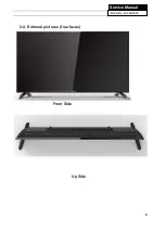
Page 9: ...9 Service Manual Model No LE39B9000 2 2 External pictures four faces Front Side Up Side ...
Page 10: ...10 Service Manual Model No LE39B9000 Right Side Back Side ...
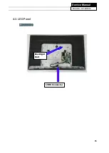
Page 15: ...15 Service Manual Model No LE39B9000 4 3 LED Panel LE39B9000 Backlight Unit LVDS Connector ...
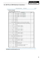
Page 16: ...16 Service Manual Model No LE39B9000 4 4 LED Panel LVDS Interface Connections ...
Page 17: ...17 Service Manual Model No LE39B9000 Chapter 5 Installation Instructions 5 1 Accessories ...
Page 18: ...18 Service Manual Model No LE39B9000 5 2 Base Stand Assembly Instruction ...
Page 19: ...19 Service Manual Model No LE39B9000 ...
Page 20: ...20 Service Manual Model No LE39B9000 ...
Page 31: ...28 Service Manual Model No LE43B7000 Chapter 9 Trouble shooting 9 1 Trouble shooting ...
Page 32: ...29 Service Manual Model No LE49B7000 ...
Page 33: ...30 Service Manual Model No LE49B7000 ...
Page 34: ...31 Service Manual Model No LE49B7000 ...
Page 35: ...32 Service Manual Model No LE49B7000 ...


