


Reviews:
No comments
Related manuals for Beovision MX1500

21F1 NX56E-LA
Brand: TCL Pages: 77

Connect 22
Brand: Loewe Pages: 48

CX30004-102
Brand: Precor Pages: 8

HL32K300L
Brand: Hisense Pages: 38

MD2868-LK
Brand: Mounting Dream Pages: 18

BLANDY 300
Brand: Revolution Galaxy Pages: 2

PS1980
Brand: Magnavox Pages: 32
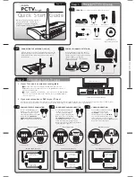
PCTV To Go
Brand: Pinnacle Pages: 2
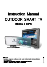
215FS
Brand: Falcon Pages: 42

SENTRY 2 SL2518RK
Brand: Zenith Pages: 34

FA-TVL-180 Series
Brand: Firgelli Pages: 12

5159
Brand: Palsonic Pages: 19

GTV2254
Brand: Gelhard Pages: 62

HDLCD1955
Brand: Sansui Pages: 50

ENLTV-3
Brand: Encore Pages: 32

CS25V10
Brand: Samsung Pages: 40

280047
Brand: Ekselans Pages: 43

AV-21BD5EE
Brand: JVC Pages: 28


