11
Service Manual
Model No.:LE39B9000
Chapter 3. Disassemble and Assemble
3-1. LE39B9000
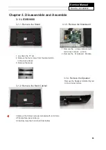
3-1-1. Remove the Stand 3-1-3. Remove the Mainboard
1. Remove the screws indicated with
red circles in above picture.
2. Remove the Mainboard Module.
1. Lay down the TV set .
2. Remove the four screws from the stand which
in the picture above,
3. Remove the stand.
3-1-4. Remove the Speaker
Remove the Speaker indicated by red
circle in below picture
3-1-2. Remove the Back Cabinet
1.Remove the thirteen screws indicated with red circles.
2.Flip machine, panel side up.
3.Carefully raise the Front shell from bottom.
Summary of Contents for LE39B9000
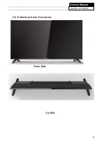
Page 9: ...9 Service Manual Model No LE39B9000 2 2 External pictures four faces Front Side Up Side ...
Page 10: ...10 Service Manual Model No LE39B9000 Right Side Back Side ...
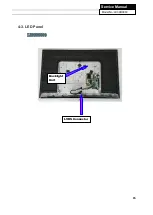
Page 15: ...15 Service Manual Model No LE39B9000 4 3 LED Panel LE39B9000 Backlight Unit LVDS Connector ...
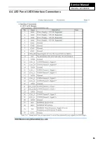
Page 16: ...16 Service Manual Model No LE39B9000 4 4 LED Panel LVDS Interface Connections ...
Page 17: ...17 Service Manual Model No LE39B9000 Chapter 5 Installation Instructions 5 1 Accessories ...
Page 18: ...18 Service Manual Model No LE39B9000 5 2 Base Stand Assembly Instruction ...
Page 19: ...19 Service Manual Model No LE39B9000 ...
Page 20: ...20 Service Manual Model No LE39B9000 ...
Page 31: ...28 Service Manual Model No LE43B7000 Chapter 9 Trouble shooting 9 1 Trouble shooting ...
Page 32: ...29 Service Manual Model No LE49B7000 ...
Page 33: ...30 Service Manual Model No LE49B7000 ...
Page 34: ...31 Service Manual Model No LE49B7000 ...
Page 35: ...32 Service Manual Model No LE49B7000 ...


