System Superheat
Return Air Temperature (
)
̧
Ambient
Temperature At
Condenser Inlet
(
)
̧
65
70
75
80
85
60 17
25 30 33
37
65 13
19 26 32
35
70 5
14 20 28
32
75 5
10 17 25
29
80
5 12 21
26
85
5 10 17
20
90
7 12
18
95
5 5
5
100
5 5
Table
7
-2:System charging table by superheat
7.8 ELECTRICAL WIRING
.
19
! WARNING
A means of strain relief must be installed to this appliance at the electrical service entrance.
The
interconnecting wires between indoor and outdoor units
must be in accordance with the national
electric code and all code
regulations.
Failure to follow these codes or the use of unsupported practices
or procedures, could result in damage or personal injury or death.
Do not use
temporary
power cord
s
and do not connect
multiple devices to the same electric
circuit
.
Such
could cause a fire or an electric shock due to
circuit overloads.
All
electrical work
should be performed by knowledgeable personals according to national
codes, and in accordance with this installation manual.
Ground the unit.
According to the national electric code.
Electrical installation consists of power supply wiring to the condensing unit and control
wiring between
thermostat, indoor unit and the condensing unit. All wiring must be in
accordance with National
Electrical Code and/or local ordinances that may apply
.
(See unit wiring diagram furnished with this instruction).
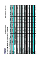
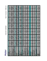
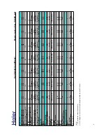
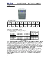
The condensing unit rating plate and the tables of "Physical and Electrical Specifications / Outdoor Units"
(Table 2-1 and 2-2) provide pertinent data necessary for the selection of proper
ampacity.
size electrical service and
over-current protection devices.
Table 7-3
provides data on the minimum copper wire size as a function of supply wire length and circuit
Central Air Conditioner
Model: Cooling Only,
13
SEER
units

