(Refer to the unit installation instructions for the specifics)
ELECTRICAL
9
.
1
INSTALLATION AND SERVICE CHECKLIST
23
vacuum pump
equipment problem is sometimes caused by an improper installation. By completing this checklist the
conditioning system call for your records.
7. A micron meter (not shown)
9. Refrigerant recovery /recycling equipment
6. An electronic leak detector or bottle of soap suds.
8. A vacuum pump capable of pulling to 1000 microns;
Before beginning any troubleshooting procedure, complete the following installation checklist. An
problem may be found and corrected. Make copies of the checklist and complete one for every air
Fig.9-1
………….Proper equipment ground to the electrical panel
………….Correct the thermostat and subbase
………….Correct line voltage supplied to indoor and outdoor units
………….Proper disconnect switches and breakers for indoor and outdoor units
………….Correct control voltage at outdoor unit and transformer adequate for all control voltage loads
………….Correct wire size for both indoor and outdoor units.
OUTDOOR UNIT INSTALLATION
………….Unit level with proper clearances for air flow and service
…………..Proper elevation of outdoor unit
…………..Solid pad
REFRIGERANT LINES
………….Proper length according to manufacturer’s instructions
…………..Proper size according to manufacturer’s instructions
…………..Large vapor line insulated
…………..No evidence of refrigerant leaks
…………..Coil free from dirt and debris
…………..No inadvertent oil traps and proper sloping
…………..No evidence of refrigerant leaks
…………..Unit charged according to manufacturer’s instructions
…………..No kinks or restrictions
INDOOR UNIT INSTALLATION
…………..Air ducts sealed to prevent leakage
…………..Adequate clearances for air flow and service
…………..Proper supply and return air duct size and design
…………..Correct filter(s)
…………..External static pressure_____ inches W.C.
…………. Proper air flow (about 400 CFM per ton)
…………. Correct indoor coil and accessories
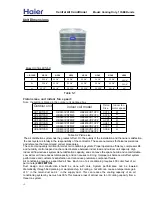
Central Air Conditioner
Model: Cooling Only,
13
SEER
units

