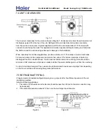


Indicator
Fig.
9
-3
25
1. Be sure power is off to the motor.
2. Disconnect the motor wires.
3. Place one ohmmeter lead on
common
and the other on
start
.The meter should show continuity.
4. Place one ohmmeter lead on
common
and the other on
run
. The meter should show continuity with
less resistance.
5. Leave one meter lead on c
ommon
and touch each remaining lead. Each should indicate continuity.
6.
7.
MECHANICAL
ELECTRICAL CHECK TO TEST FAN MOTOR:
If a winding does not show continuity, the motor has failed and must be replaced.
may be caused by excessive water. Lubrication can be washed out of permanently lubricate bearing.
If the motor needs replacing, replace the capacitor as well.
Fan motors can fail for a number of reasons, including failure bearing loss due to a lack of lubrication. This
If a motor fails, replace it with cimilar motor having the same rotation horse power, RPM and electrical
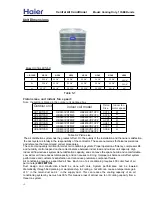
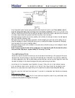
CONDENSER FAN BLADE LOCATION
Dimension “A” will be from 2” to 4” depending on the unit model number. Be sure to check this
dimension BEFORE removing the fan blade.
Note: When parts combination results in motor /blade interference ,the fan blade should be
located to provide 1/8” motor /blade clearance.
RELAYS
ELECTRICAL OPERATION
Contactor coils are made with copper wires wrapped around a steel core. When energized, the coil
generates a magnetic field that moves the steel core to open or close the circuit contacts. Electrical
continuity
indicates a good coil. Relay coils use specific voltage. Using
a contactor with
the wrong voltage
coil will prevent the system from operating properly. This problem is avoided when using the proper
replacement part for a failed component.
characteristics.
Fi
g. 9
-4
can generate enough heat to weld the contacts together. Physical examination of the contacts
Relay contacts are switches and can become pitted or corroded, creating resistance. Resistance
Central Air Conditioner
Model: Cooling Only,
13
SEER
units


