


9
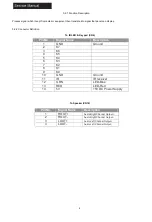
3-2-1 Function Description
Process signal which incept from exterior equipment then translate into signal that panel can display.
3-2-2 Connector Definition
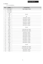
To IR LED & Key pad (CN6)
To Speaker (CN18)
Pin No.
Signal Name
Description
1
GND
Ground
2
K7
3
K6
4
K5
5
K4
6
K3
7
K2
8
K1
9
K0
10
GND
Ground
11
IR
IR receiver
12
GRN
LED-Blue
13
RED
LED-Red
14
5V
+5V DC Power Supply
Pin No.
Signal Name
Description
1
ROUT+
Audio Right Channel
2
ROUT-
Audio Right Channel Output-
3
LOUT+
Audio Left Channel
4
LOUT-
Audio Left Channel Output-
Summary of Contents for 24E2000
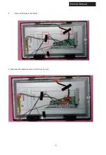
Page 13: ...12 3 Remove all tapes on the cables 5 Disconnect the cables and remove them from the unit ...
Page 15: ...14 Manual 4 Accessories Remote Control 2 x AAA Batteries User Manual ...
Page 18: ...17 Connecting a PC VGA Supported timing ...
Page 19: ...18 Service Manual Connecting AV Equipment COMPONENT OUT ...
Page 21: ...20 Cable Sample Note The cables are not included in the package ...
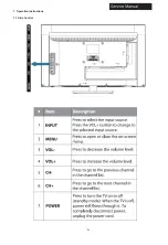
Page 22: ...21 7 Operation Instructions 7 1 Side Control ...
Page 23: ...22 7 2 Rear Terminals Connector Descriptions Ser 9 P r e s s t o o p e n t h e ...
Page 24: ...23 t e l e t e x t C C 7 3 Using Remote Control ...
Page 25: ...24 8 Electrical Parts 8 1 System Block Diagram ...
Page 26: ...25 8 2 Circuit Diagram ...
Page 27: ...26 ...
Page 28: ...27 ...
Page 29: ...28 ...
Page 30: ...29 ...
Page 31: ...30 ...
Page 32: ...31 2 2 0 ...
Page 34: ...33 9 Measurements and Adjustment 9 1 Operation Guide ...
Page 35: ...34 ...
Page 36: ...35 ...
Page 37: ...36 ...
Page 38: ...37 ...
Page 39: ...38 ...
Page 40: ...39 ...
Page 44: ...43 10 2 System Power Check ...
Page 45: ...44 10 3 No Sound No Picture ...
Page 46: ...45 10 4 Audio Problem ...


