background image

NOTES

1) "O"  Terminal is energized for cooling

"B"  Terminal is energized for heating

In most applications, the reversing valve is energized for cooling
and should be connected to the "O" terminal.  If the heat pump 
requires the reversing valve to be energized for heating, connect 
the reversing valve to the "B" terminal.

2) "X1" and "X2" are connected to a 24VAC Red LED, most often 

used to indicate a fault with the heat pump compressor.

3) The Emergency Heat Relay (E Terminal) and outdoor

thermostats (usually accessories to a heat pump), are not used.
The RC-100 automatically controls auxiliary heat efficiently.

The RC-100 requires at least 1 stage of auxiliary heat enabled at
all times.  If the heat pump is equipped with an outdoor
thermostat, it should be removed from the auxiliary heat circuit,
or reconfigured so that it can only disable 2nd and 3rd stage of
auxiliary heat.

DISABLE KEYS

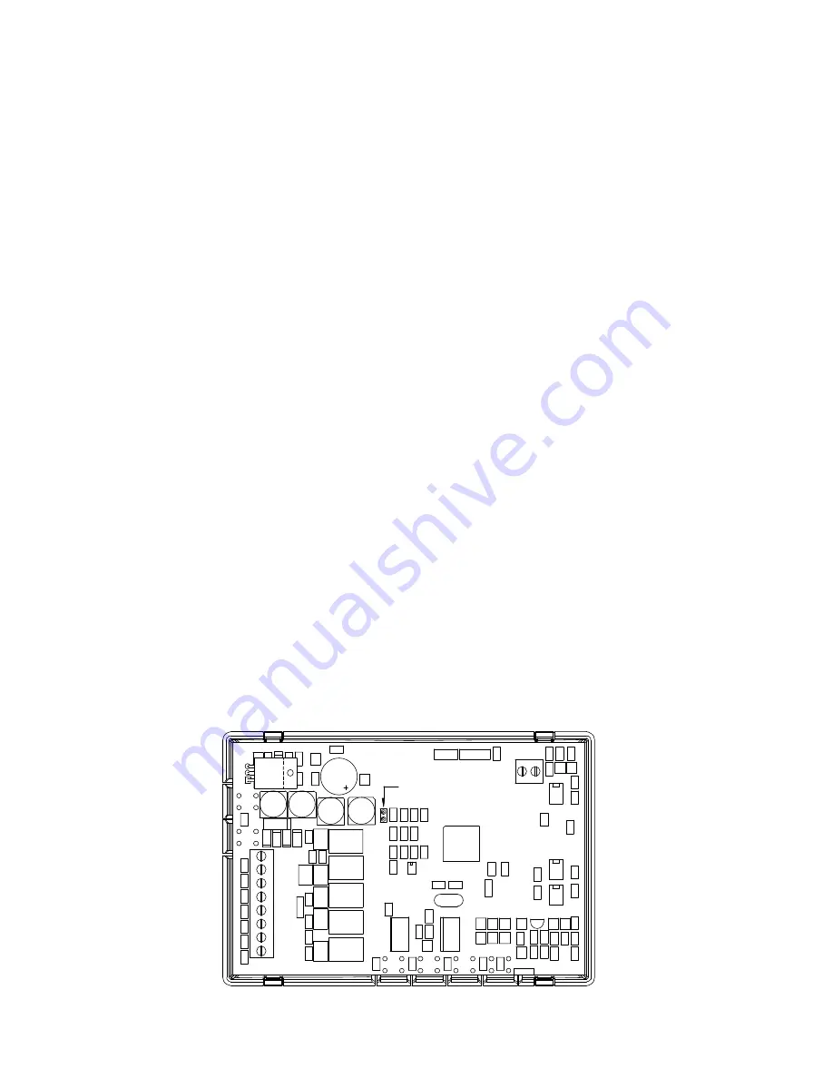
The keys on the thermostat can be disabled to prevent anyone from
controlling the thermostat locally.  To disable the keys, solder a wire
jumper across the two holes on the circuit board as shown below.

8

SOLDER WIRE

JUMPER HERE

Summary of Contents for RC-100

Page 1: ...O M N I S T A T ELECTRONIC COMMUNICATING THERMOSTAT Installation Manual RC 100 Heat Pump 2 Stage Heat 1 Stage Cool Document Number 13I00 3 January 1997...

Page 2: ...N EXISTING THERMOSTAT 2 MOUNTING 3 WIRING DIAGRAMS 6 DISABLE KEYS 8 POWER UP 9 INSTALLER SETUP 10 OWNER S MANUAL 15 QUICK REFERENCE SETUP GUIDE 16 REMOTE SYSTEM WIRING DIAGRAMS 17 TROUBLESHOOTING TIPS...

Page 3: ...e installed in accordance with National wiring rules for the country in which it is installed 2 Fuses must be replaced only with IEC rated components 3 All product labels instructions and markings rel...

Page 4: ...at the thermostat is located in an area where there is adequate air circulation 3 Do not mount in the path of direct sunlight or of radiant heat generated by appliances 4 Do not mount behind an outdoo...

Page 5: ...is upright and facing you 1 Mark the two mounting holes on the wall using a pencil 2 Drill a hole using a 3 16 bit at each mounting hole marking 3 Install the two wall anchors supplied 4 Slide the sys...

Page 6: ...at wiring If a remote system is being used with the thermostat connect the remote system wiring to the supplied cable using the wire splices per the diagram for your remote system application See Figu...

Page 7: ...hermostat face into the thermostat base locking it into place See Figure 3 Figure 3 Mounting thermostat face to thermostat base Note Be sure that the thermostat temperature sensor is standing up and t...

Page 8: ...pressor relay reversing relay aux heat relay fan relay or fault relay even momentarily This will blow a non replaceable fuse 3 Do not attempt to hook up to live circuits An accidental connection to a...

Page 9: ...MER 24VAC 1 2 3 4 5 6 7 8 W2 Y RELAY COMPRESSOR RELAY FAULT X2 X1 24VAC HOT 24VAC COMMON HEAT PUMP SYSTEM RC 100 W2 B Y C O G R L 24VAC HOT FAN ENERGISED IN COOL MODE ENERGISED IN HEAT MODE 24VAC COMM...

Page 10: ...E Terminal and outdoor thermostats usually accessories to a heat pump are not used The RC 100 automatically controls auxiliary heat efficiently The RC 100 requires at least 1 stage of auxiliary heat e...

Page 11: ...comes on in heating mode After a few minutes set the mode to EM HEAT The heat pump should stop and the auxiliary heating should come on Set the mode to OFF Ensure that both the heat pump and auxiliary...

Page 12: ...e display are the value of the item number 3 Press the Prog key to advance to the next item 4 Press the Hold key to return to the previous item 5 Use the arrow keys to change the value of each item 6...

Page 13: ...n communicate with remote systems in 4 different modes These modes are 0 300 baud RS 232 mode for use with personal computers 1 100 baud System mode Omni OmniPro and Aegis systems 8 PESM mode use with...

Page 14: ...Energy Efficient Control EEC of Auxiliary Heat Select 0 1 4 5 to enable EEC or 8 9 12 13 to disable EEC display See Owner s Manual for description of EEC The default setting is 1 12...

Page 15: ...e 3 Fahrenheit 24 hour time format programmable 4 Celsius am pm time format non programmable 5 Fahrenheit am pm time format non programmable 6 Celsius 24 hour time format non programmable 7 Fahrenheit...

Page 16: ...ting is 91 07 Not used 08 Not used 09 Not Used 10 Not Used 11 Cooling minimum on off time minutes This item is used to limit the on and off times of the cooling system When the cooling system starts i...

Page 17: ...atic anticipator will compensate for the temperature droop caused by the stage 2 differential under cold weather conditions 14 Clock adjust If the clock on the thermostat is running faster or slower t...

Page 18: ...tem was in operation last week ANTICIPATION RC 100 anticipation is performed electronically and is independent of the type and load of the components in the heating and cooling equipment The RC 100 ha...

Page 19: ...umber Description Default Current 00 Address 1 01 Communication mode 1 02 System options 1 03 Display options 1 04 Calibration offset 30 05 Cool setpoint limit 51 06 Heat setpoint limit 91 07 Not used...

Page 20: ...ode cool setting heat setting status of fan and hold and other items Run a 3 or 4 conductor wire from the HAI system to the thermostat location All thermostats on an Omni OmniPro or Aegis controller a...

Page 21: ...p item 01 Communications mode must be set to 24 Run a two conductor wire from the remote system or remote switch to the thermostat location Make the connections using supplied wire splices See Figure...

Page 22: ...ostat REMOTE is displayed when system is overriding thermostat Disconnect the cable from COMM connector to test SYMPTOM ACTION TO TAKE Can t Adjust Temperature 1 Mode is Off Select Heat Cool or Auto 2...

Page 23: ...Too Often 1 Heat Pump is not able to meet load due to cold weather 2 Thermostat is in EM Heat mode Set thermostat to Heat or Auto mode In EM Heat mode the auxiliary heat is turned on SYMPTOM ACTION T...

Page 24: ...R 867 PH50 R G O C Y W1 W2 LENNOX HP19 HP20 V VR F R X M Y L LENNOX CB19 R G O C Y W1 L RHEEM RUDD PGB PFA PCB R G O X Y W2 L WEATHERTRON R G O B Y W U YORK E1CS E1FB E1FH R G O B Y W X RC 100 TERMINA...

Reviews: