background image


Page 14 

Configuring Keypad Controllers 

 
The 6-Button and 8-Button Keypad Controllers can be configured by UPStart to perform various functions.  The keypad controllers 
can be configured to operate as general purpose keypads under the control of OmniLT.  When set up as follows, the keypad controller 
will send a message to the OmniLT controller any time a button is pressed.  The state of the corresponding LED will not change.  
OmniLT has complete control of the LED. 


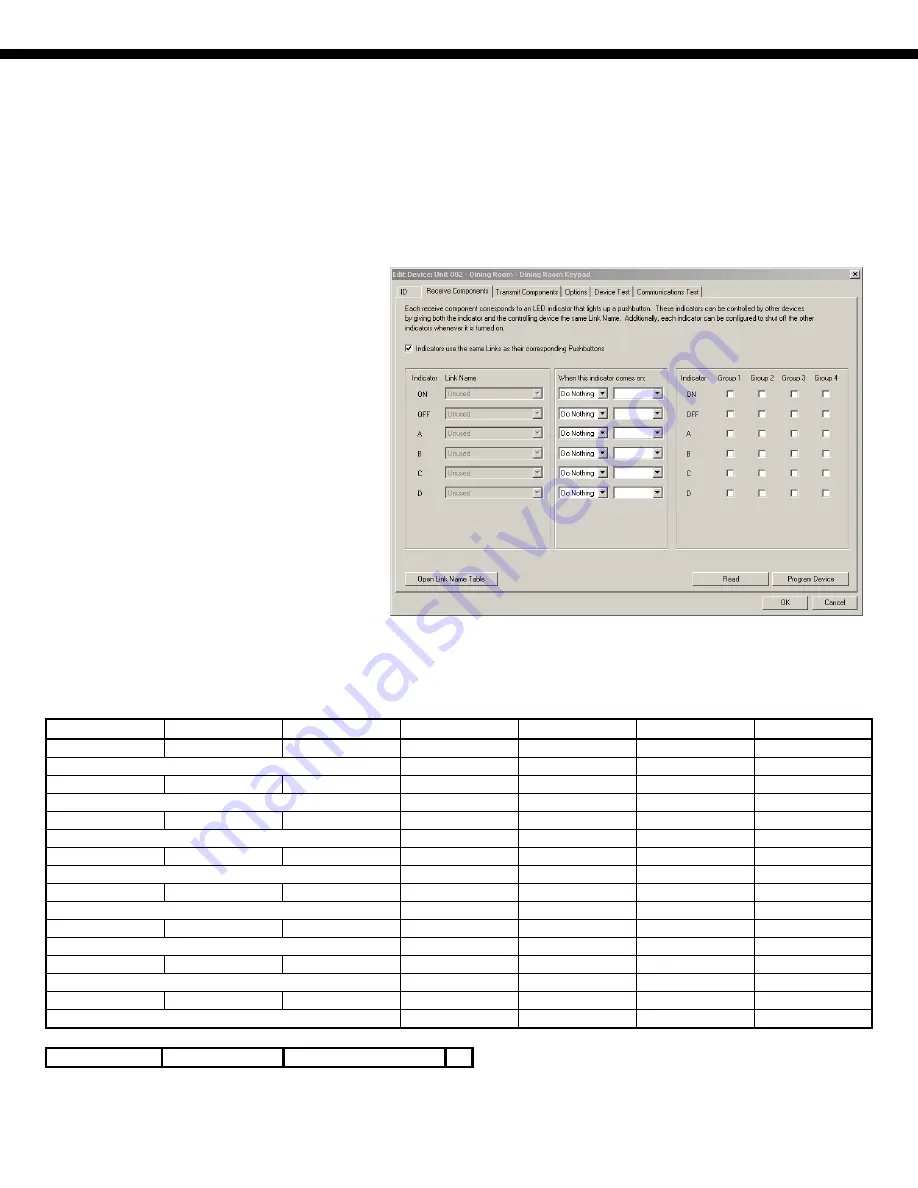
Set the Receive Components as follows: 


1.


Check "Indicators use the same Links as their 
corresponding Pushbuttons". 

 
2.


For complete control of the LEDs by the 
OmniLT controller, uncheck all "Turn  
other indicators off" setting to make certain  
that indicators are not mutually exclusive.   
 
Newer versions of the 6-Button and 8-Button 
Keypad Controllers and UPStart software may 
support more extensive LED Group control 
settings.  For complete control of the LEDs by 
the OmniLT controller, select “Do Nothing” 
under “When this indicator comes on:” for  
each Indicator and uncheck all Group options. 


For the 6-Button Keypad Controller, set the Transmit Components as follows: 


Button Link 

Name Mode 

Single-Tap Double-Tap Hold 

Release 

On 

Switch 

1/On 

Custom 

Button 

Null Null No 

Command 

Null 


Null Null No 

Command 

Null 

Off 

Switch 

2/Off 

Custom 

Button 

Null Null No 

Command 

Null 


Null Null No 

Command 

Null 

Switch 

3/A 

Custom 

Button 

Null Null No 

Command 

Null 


Null Null No 

Command 

Null 

Switch 

4/B 

Custom 

Button 

Null Null No 

Command 

Null 


Null Null No 

Command 

Null 

Switch 

5/C 

Custom 

Button 

Null Null No 

Command 

Null 


Null Null No 

Command 

Null 

Switch 

6/D 

Custom 

Button 

Null Null No 

Command 

Null 


Null Null No 

Command 

Null 

UP 

Unused 

Null Button 

No Command 

No Command 

No Command 

No Command 


No Command 

No Command 

No Command 

No Command 

DN 

Unused 

Null Button 

No Command 

No Command 

No Command 

No Command 


No Command 

No Command 

No Command 

No Command 


Transmit Type: 

Line Packet 

Transmission Attempts: 

Summary of Contents for OmniLT

Page 1: ...Temperature sensors can be used for outdoors or in attics garages greenhouses basements wine cellars coolers and freezers The temperature can be displayed on the console or spoken over the telephone...

Page 2: ...Page 2...

Page 3: ...multiple RadioRA Switches and Dimmers with one command To control more than one device at one time Phantom Buttons are recommended A Zone is any individual RadioRA Switch or Dimmer A RadioRA System h...

Page 4: ...such as X 10 RadioRA devices can share the same House Code with ALC devices Any unit number that is not being used for an ALC Switch Module may be used for a RadioRA device ALC Switch Modules and Radi...

Page 5: ...n t explicitly send an All On command to those units If the House Code All On or House Code All Off setup item is set to No OmniLT will not change the status of each unit on the House Code Executing P...

Page 6: ...default setting for HC 1 Format is 1 House Code 1 All Off This feature allows you to choose if House Code 1 will respond to the All Off command The default setting for HC 1 All Off is Yes HC 1 ALL OFF...

Page 7: ...ctivated event Additionally you can specify that the event will only activate when a RadioRA Switch or Dimmer is turned on or off or if a button is pressed on a Master Control You are first prompted t...

Page 8: ...Controlling RadioRA Units in this document Program Phantom Button Commands 4 ALL OmniLT can execute a Phantom Button command to set a lighting scene Press the 4 ALL key to execute a Phantom Button com...

Page 9: ...rk ID that serves to link all of the switches modules and keypad controllers to each other and to the OmniLT controller Under the Network ID each device has a unique address The address is used to sen...

Page 10: ...PB UPStart for optimal communications with the OmniLT controller Note Although the UPB protocol is extremely robust and less susceptible to powerline conditions for professional installations HAI reco...

Page 11: ...tate is then displayed Entry Lights STATUS 67 Note When a UPB signal is received over the powerline OmniLT will automatically update the status of the device All On Off UPB devices are not affected by...

Page 12: ...de rate and Wall Switch 2 to go to a different level at a different fade rate The ability to send more than one device to its preset level at a preset fade rate with a single command is known as activ...

Page 13: ...Switch Off 2 242 Switch On 3 243 Switch 1 On 4 244 Switch 2 Off 5 245 Switch 3 A 6 246 Switch 4 B 7 247 Switch 5 C 8 248 Switch 6 D 9 249 Switch 7 10 250 Switch 8 For each UPB Wall Switch Select a wa...

Page 14: ...ontrol settings For complete control of the LEDs by the OmniLT controller select Do Nothing under When this indicator comes on for each Indicator and uncheck all Group options For the 6 Button Keypad...

Page 15: ...Null Null Null No Command Null K Switch 7 Custom Button Null Null No Command Null Null Null No Command Null L Switch 8 Custom Button Null Null No Command Null Null Null No Command Null Transmit Type L...

Page 16: ...pose Mode and UPB transmission format HC 1 FORMAT 1 1 EXTENDED CHNG To change format for House Code 1 press the key then use the arrow keys to scroll through the list of formats Press the key to selec...

Page 17: ...presses and receive Links press the key to bring up a menu of event button types BUTTON TYPE 1 CTRL 2 SEC 3 ZONE 4 ALL 5 ALARM 6 X 10 7 MISC 8 MSG Control Unit Event UPB Switch Press Event Buttons 1...

Page 18: ...roller 8 Button Keypad Controller 1 2 On Button E 2 3 Off Button F 3 4 A G 4 5 B H 5 6 C I 6 7 D J 7 8 K 8 9 L Receive Link Event 4 ALL OmniLT can receive arbitrary Links from devices on the UPB netwo...

Page 19: ...er when the A button on that keypad controller is pressed This program can also be used to illuminate the G button on an 8 Button Keypad Controller when the G button is pressed Program Status Request...

Page 20: ...of units 1 4 WHEN LINK 1 ON RUN GROUP 1 WHEN LINK 2 ON RUN GROUP 1 WHEN LINK 3 ON RUN GROUP 1 WHEN LINK 4 ON RUN GROUP 1 When Link 1 4 On is received on the UPB network the Group 1 button macro is exe...

Reviews: