background image

F

i

le Menu Selec

ti

ons

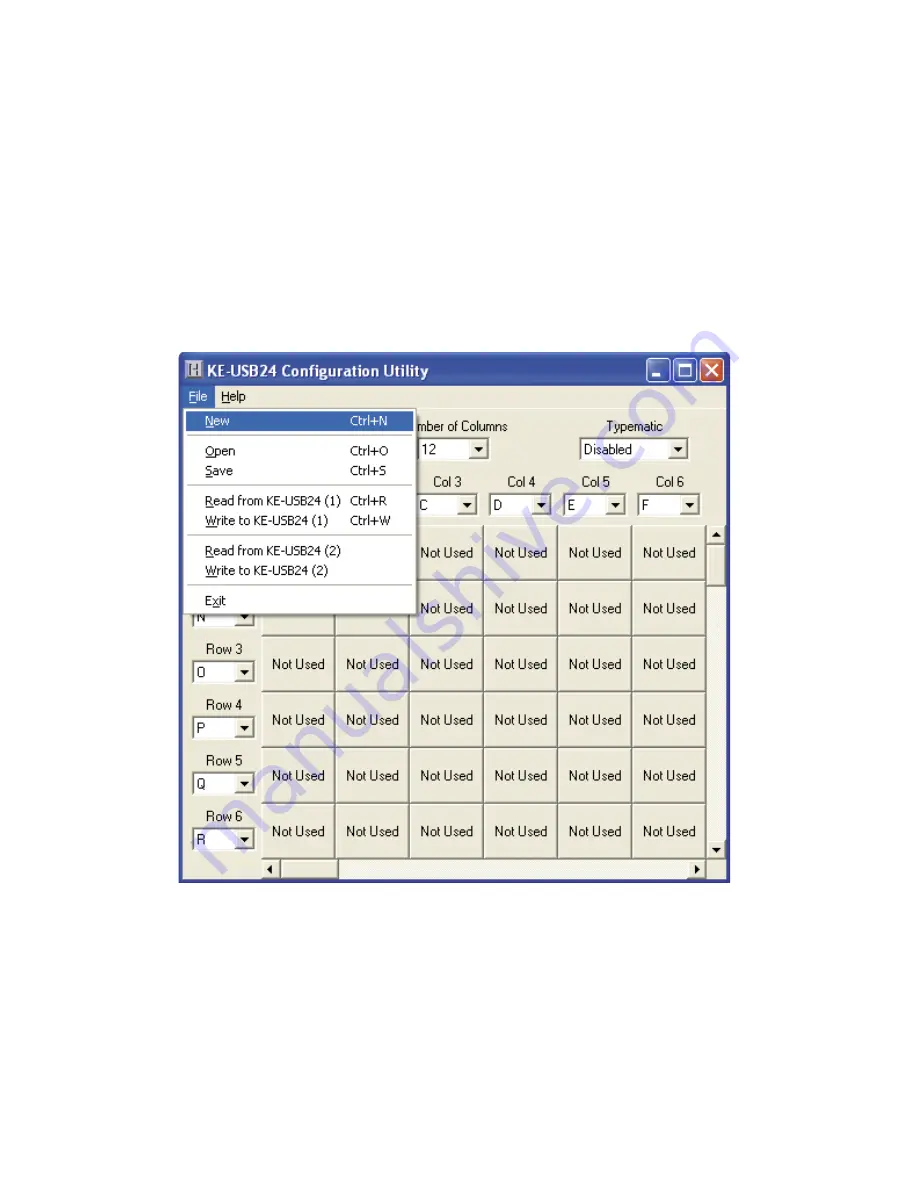
These selections, located within a drop down list, are accessed 
by clicking on “File” in the upper left  corner of the main program 
screen.  This  list provides  several  options  that include  creating 
and saving fi le confi gurations as well as reading and writing to 
the KEUSB24. A list of these options along with descriptions of 
how they pertain to the KEUSB24 setup are listed below.

7

N

e

w:

  Creates  a  new  confi guration  fi le  by  either  clicking on 

“New”  with the  mouse  or  by pressing Ctrl+N  on  the  keyboard. 
This  option  will  also return  the  program  screen  to  the  default 
settings.

1

4

The  following  diagram  shows  the  completed  setup  created  in 
this example. Note the presence of modifi er keys in Row 4, Col 
3 and Row 4, Col 4.

Summary of Contents for KEUSB24

Page 1: ...KEUSB24 PC Keyboard Encoder User Manual ...

Page 2: ...nu Selections 7 Sample KEUSB24 Configuration 9 Error Messages 16 KEUSB24 Operating Tips 18 Appendix A Specifications 19 Appendix B Command Line Loader 20 Accessories 20 Thank you for purchasing the HAGSTROM ELECTRONICS INC KEUSB24 This product is configurable in a variety of ways to meet your specific requirements Please take a few minutes to read this manual before using your KEUSB24 G o p th N o...

Page 3: ...t can be programmed to scan any size matrix up to 12 Columns x 12 Rows Any of the 24 I O pins may be designated as either a Column or a Row The KEUSB24 configures its scanning to the keypad allowing the direct connection of many off the shelf keypads without any modified or complicated cabling Power Requirements The KEUSB24 requires no external power source It is powered directly from the USB port...

Page 4: ...SB keyboard and may be used in addition to or in place of the system s own keyboard Device ID Jumper Two KEUSB24 units may be connected to the same computer and programmed independently If using one unit leave the Device ID jumper open factory default If using two KEUSB24 units leave the jumper open on unit 1 and closed on unit 2 This setup will present two different USB devices to the system that...

Page 5: ...es are initiated by shorting a Row pin to a Column pin through a contact closure The pins that are defined as Columns will sink current while scanning the matrix The Rows are used to read the status of the inputs when a Column is active Note The switch keypad or input device that is used must be capable of carrying at least 1mA of current In addition to switches and keypads other electronic circui...

Page 6: ...uter Connections 2 Insert the CD and save the content to its own folder on the hard drive The CD may now be removed and stored in a safe location for future use 3 Open the folder that was created in step 2 and start the configuration program by selecting the program file KEUSB24 EXE Note The programs must be copied to and run from its own folder on the PC s hard drive The CD itself should be reser...

Page 7: ...ed below Note The number of Rows plus the number of Columns cannot exceed the total number of 24 I O pins For example 5 Rows 12 Columns 17 I O pins Number of Rows The number of Rows are selected from the drop down list This may be any value from 1 to 23 Number of Columns The number of Columns are selected from the drop down list This may be any value from 1 to 23 5 e e f h n m r l g m e ...

Page 8: ...okes being generated from the devices attached to the KEUSB24 will produce one keystroke per activation Note The Typematic Enable Disable option only applies to the devices connected to the KEUSB24 I O header It will not affect the repeat functions of the PC keyboard Column Pin Assignments Column pin assignments are selected from their corresponding drop down list Each column must have an I O pin ...

Page 9: ...t include creating and saving file configurations as well as reading and writing to the KEUSB24 A list of these options along with descriptions of how they pertain to the KEUSB24 setup are listed below 7 New Creates a new configuration file by either clicking on New with the mouse or by pressing Ctrl N on the keyboard This option will also return the program screen to the default settings n l ...

Page 10: ... Write to KEUSB24 1 This option will write the current configuration displayed on the screen to the KEUSB24 The KEUSB24 can be programmed and re programmed as many times as necessary Click on Write to KEUSB24 with the mouse or press Ctrl W on the keyboard to perform this operation After the KEUSB24 has been loaded with the new configuration it will scan according to this new setup Read from KEUSB2...

Page 11: ...w to program the KEUSB24 to scan a keypad The keypad in the example is a 4x4 matrix 16 key device Step 1 Select the Number of Rows on the screen and set it to 4 Select the Number of Columns and set that value to 4 as well The screen should appear as shown below 9 e s n ...

Page 12: ...ple the header pins A through H are used as the connection point Note Any 8 of the KEUSB24 pins could have been used for this example Since the Columns and Rows for the example keypad are intermixed the pin definitions for the Rows and Columns must be assigned Highlight the Column pin designations and assign them as follows Col 1 Pin D Col 2 Pin A Col 3 Pin G Col 4 Pin H Select the Row Pin definit...

Page 13: ... Opinsselected assign the keys to be emulated to each position in the matrix To assign keys click on the desired matrix position A diagram of the keyboard will be displayed as shown below Click on the representation of the key to assign it to the matrix position 11 ...

Page 14: ...e selecting each position in the matrix and assign the desired keys from the keyboard diagram until the matrix is finished In the example illustrations the user clicked matrix position Row 1 Col 3 and assigned the key C to it ...

Page 15: ...o create this input check the Ctrl and Alt boxes on the lower left corner of the keyboard diagram then click on the Del button shown below Any position in the KEUSB24 matrix can be modified by one or a combination of two of the Shift Alt or Ctrl keys using the method described above Use the Shift function to generate upper case characters or shifted characters etc in the application To remove one ...

Page 16: ...T b s a t h N T s 14 The following diagram shows the completed setup created in this example Note the presence of modifier keys in Row 4 Col 3 and Row 4 Col 4 ...

Page 17: ...o disk Specify a file name under which to save the configuration Step 6 Load the KEUSB24 with the configuration Be sure that the KEUSB24 is connected to the PC Once the KEUSB24 is loaded it will begin running the new setup 15 r C r s e d s l o t e n d n a a ...

Page 18: ...nfiguration Communication may be interrupted if a user presses a key on the keyboard or if another program takes the focus away from the KEUSB24 application If this error message is displayed load the configuration again 16 Invalid configuration Invalid configuration file When loading an already existing configuration from a file or uploading a configuration from the KEUSB24 the program will give ...

Page 19: ...ile again Error Pin is used for multiple scan lines If a header pin is used to designate more than one row or column or is used for both a row and a column this error will be displayed when saving the configuration to a file or to the KEUSB24 Check the matrix configuration and eliminate redudant pin letters The error message will give the letter of the problematic pin Example Error Pin D is used f...

Page 20: ...ctions from the switches or keypads to the KEUSB24 I O header If using a Device ID jumper only make changes to it when the power to the unit is off as it is sampled at power on or reset While the KEUSB24 only scans a matrix running a 1 x 23 matrix essentially provides 23 individual inputs without the inherent matrix issues Note For any questions that are not answered in this manual please send us ...

Page 21: ...erating Current 12 ma Typical Operating Temp 0 to 70 Degrees C PC Interface USB Input Debounce Time 15 20 Msec Typical I O Header 24 I O up to 12x12 Matrix programmable Appendix A KEUSB24 Specifications 2 0 2 5 125 Dia 4 19 on ts rd wn ...

Page 22: ...B24 header Features a right angle connector that plugs directly to the I O header and provides 12 inches of discrete wire for each header pin MTA100 12 12 KEUSB24 Header Appendix B Command Line Loader The KEUSB24 can also be loaded through the command line by using the supplied KEUSB24LOAD EXE program Refer to readme txt located under the Command Line Loader folder on the supplied CD ROM for furth...

Page 23: ...r warranty Depending on the state in which you live you may have additional rights Great care has been taken during the assembly testing and burn in of your KEUSB24 to ensure its performance If you have any questions please send us an email or give us a call Support is available Monday through Friday 8 00 am to 5 00 pm EST customer service email sales hagstromelectronics com Call Toll Free 888 690...

Page 24: ...5 4677 Fax 540 465 4678 Monday through Friday 8 00 am to 5 00 pm EST sales hagstromelectronics com www hagstromelectronics com 1986 Junction Road Strasburg VA 22657 Copyright 2017 HAGSTROM ELECTRONICS INC V 07 16 HAGSTROM ELECTRONICS INC ...

Reviews: