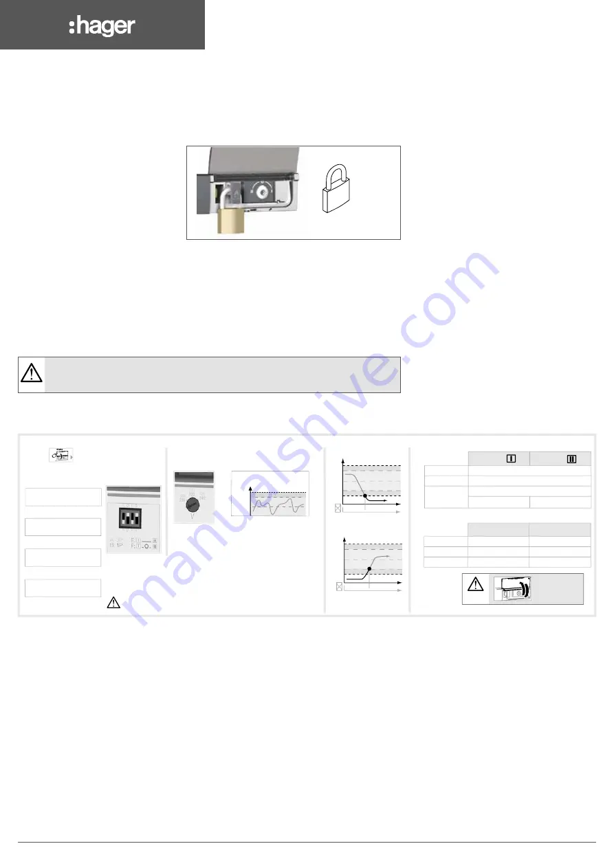
background image

6LE007621A

22

11.4. 

Padlocking

Enables locking in the 0 position (factory configuration) or in positions I, 0 or II (user configurable).

It is necessary to configure padlocking to all positions before installation as access to configuration is at 

the back of the product. Refer to section "7.1. Changing the padlocking configuration", page 11


Locking is only possible in manual mode 

(cover open).

Pull on the locking handle to enable the 

interlock. Lock by inserting a padlock into 

the orifice provided for this purpose.


4 mm min

8 mm max


11.5. 

Programming

Whilst in manual mode check the wiring and installation. If ok power up the product.

This product must always be put into service by qualified and approved personal.

The LED signalling is only active when the product supply is on (supply LED lit).

To set the dip switches, it is necessary to open the AUTO/MANU cover.

The commissioning must always result in having at least 1 LED source available lit.

Therefore, the voltage and frequency must be within the defined thresholds.

Any action on the potentiometers changes the settings, even if the cover is closed.

11.5.1. Single phase version


207208209210 63 64 73 74

22

44

66

88

11

33

55

77

22

44

66

88

11

33

55

77

2

4

6

8

1

3

5

7

2

4

6

8

1

3

5

7

/

I1 I2 I3

O1 O2

5 A AC1 / DC1

250 Vac / 30Vdc

22 24 21

11 14 12

01 04 02

In order to 

padlock put 

the product in 

manual mode.
Pull the locking 

mechanism and insert a padlock 

as shown.
As standard padlocking in the O 

position. Configurable to I - O - II 

(see step 1).

Installation

Control / aux power terminals and wiring

Recommended orientation

116

324

26

245

143

350

13

53

46

73,5

18

45

MAX : 2

x2

x2

X8

Click!

 Automatic 

operation

PROGRAMMING

(

Manual operation)

Power terminal connections

Manual 

operation

Padlocking mode

Check

Dip switch settings

Type of network: A-B

Frequency: C-D

Stop in O position: E-F

Type of application: G-H

Source voltage supply configuration

Padlocking configuration

LED's info

Timer settings

Source  

Source 

LED ON

available

LED OFF

missing or out of range

LED blinking

-  a timer is counting down
- test mode

A: 3P

B: 1P

C: 50 Hz

D: 60 Hz

E: No stop in O position

F: 2 s stop in O position

G: Network / Genset

H: Network / Network

Load side bridging bars

125A: HZI400

160A: HZI401

Voltage taps provide 2x ≤ 1.5 mm

2


connections.

They can be fitted in any terminals on the 

source supply side.

Do not use on the load side when 

equipped with a bridging bar.

Close the front cover as shown 

to put the product into automatic 

mode.

Source supply 

side

Ensure that the product is in manual mode 

(front cover open).

DIN RAIL IEC 60715

131,5

47

326

131,5

52

104

176

Auxiliary contacts:


Fitting of auxiliary contacts: 

HZI300.

To fit an AC, the switch must first 

be put in position O. An auxiliary 

contact module comprises: one 

NO / NC changeover contact for 

each position (I-O-II). To install use 

the long screws supplied with the 

module.

Recommended

Ok

Ok

Ok

Ok

Ok

I

O

II

I

O

II

Step 1

Step 2

Step 3

1

2

4

5

6A

6B

6C

3

(Max 8 Nm)

Extension

To simplify 

operation use 

the handle 

with the 

extension 

provided.

Open the front 

cover as shown 

to put into 

manual mode.
Use the handle situated in the 

front panel under the cover to 

operate the transfer switch.

Check the changeover switch 

position on the indicator before 

operating.

LOAD

&

é

"

'

HYST

HYST

+∆U/

+∆F

+∆U/

+∆F

Un

HYST: 20 % ∆U/F


ΔU: 5 - 20 %


ΔF: 3 - 10 %

Ensure that the product is 

installed on a flat rigid surface.

Tighten to avoid movement on the 

DIN rail.

The HIC4xxA is 

delivered with 

padlocking 

configured to the 

O position.

To allow padlocking in all 

positions (I - O - II), configure 

the HIC4xxA as follows 

before installation. (Screw 

is located at the back of the 

product).

It is essential 

to tighten 

all terminals 

including those 

not being used.

Whilst in manual 

mode, check the 

wiring and if ok power 

up the product.

6LE003168Ad

3

6LE003168Ad

2

Type

Terminal 

no.

Application

Status of the 

contact

Description

Output 

characteristics

Recommended 

connection 

cross-section

Inputs

207

Common

6 mm

0.5 to 1.5 mm

2

6 mm

0.5 to 2.5 mm

2

3

0.5 Nm

208

I1

Network / Network

With priority

Dry potential free 

contact

Without priority

Network / Genset

Automatic retransfer
Manual Retransfer

209

I2

Network / Network

Source priority I
Source priority II

Network / Genset

Stop the test on load
Test on load

210

I3

Network / Network 

or Network / Genset

AUTO mode
Automatic mode 

inhibition

Outputs 63 / 64

O1

Network / Network 

or Network / Genset

Product not available:

- Manual mode

- Operation failure

- Electronic failure

- No power sources

Resistive load

2A 30Vdc

0.5A 230Vac

Pmax:  

60W or 125VA

Umax:  

30Vdc or 230Vac

Product available

73 / 74

O2

Network / Genset

No start command genset
Generating set starting

90°

90°

LOAD

Type

Terminal 

no.

Status of the 

contact

Description

Output 

characteristics

Recommended 

connection 

cross-section

Auxiliary 

contact 

block

HZI300

11/12/14

11

14

12

Changeover switch in 

position I

250Vac 5A AC1

30Vdc 5A DC1

10 mm

0.5 to 1.5 mm

2

10 mm

0.5 to 2.5 mm

2

2.5

21/22/24

21

24

22

Changeover switch in 

position II

01/02/04

01

04

02

Changeover switch in 

position O

Un (P-P):  

380-420 Vac

Un (P-N):  

220-240 Vac

Loss of priority 

source timer

Return of priority 

source timer

6 mounting brackets 6x M6 screw - 2.5 Nm

MRT

Source availability LED's

Fault and state of the product LED's

q

AUT

LED ON

Fault

Auto mode

LED OFF

Product OK

Manual mode

LED blinking

Wait

Manual retransfer

MFT

MFT: 0-60 s

U/F

[HYST]

[HYST]

MRT: 0-30 min.

U/F

6 mm

6 mm

0.5 to 1.5 mm

2

0.5 to 2.5 mm

2

4

5 Nm

15 mm

15 mm

10 to 70 mm

2


The LED signalling and operation is only active when the product supply is 

available. To set the dip switches, it is necessary to open the Auto/Manual 

cover. Commissioning must always result in having at least 1 LED source 

available on. (Therefore, the voltage and frequency must be within the defined 

thresholds).

  Any action on the potentiometers will change the settings, even when 

the cover is closed.

1

0

2

0

Fault Reset

Use 20 mm screws for 1 module
Use 35 mm screws for 2 modules

1 Nm

PZ1

0.25 Nm

PZ2

0.25 Nm

PZ2

3.5

0.45 Nm

1 Nm

PZ2

1 Nm

PZ2

4-8 mm


Summary of Contents for HIC4 A Series

Page 1: ...6LE007621A z Automatic Transfer Switching Equipment Instruction manual HIC4xxA 6LE007621A 1...

Page 2: ...optional accessories 12 8 1 Auxilliary contacts 12 8 2 Voltage sensing and power supply tap 12 8 3 Bridging bars 4P 13 8 4 Terminal shrouds 13 8 5 Sealable cover 13 9 Connection of the power circuits...

Page 3: ...5 1 Single phase version 22 11 5 2 Three phase version 23 11 6 Sealable configuration cover 24 11 7 Automatic mode 24 11 7 1 Sealable Auto Manual cover 24 11 8 Possible actions 24 11 9 Manual Automat...

Page 4: ...opean Directives governing this type of product and includes CE marking on each product No covers other than that for auto manu on the HIC4xxA should be opened with or without voltage as there may sti...

Page 5: ...ety between a normal and an alternate source A complete product delivered as a fully assembled and tested solution Intuitive HMI for emergency local operation Integrated and robust switch disconnectio...

Page 6: ...II Monitoring 3 voltages on networks I and II Frequency on networks I and II Automatic controller configuration By potentiometer and micro switch Vn Fn V threshold F threshold Driving with or without...

Page 7: ...switch with the motorisation on the right hand side as shown 3 2 Specifications and advantages 1 Power section A fully integrated and interlocked transfer switch with high electrical performance offe...

Page 8: ...0 Bridging bars To provide a common point on the outgoing side of the switch load side Three phase product Rating 125A HZI400 Rating 160A HZI401 Terminal shrouds Protection against direct contacts wit...

Page 9: ...N fuses Fuse protected short circuit withstand kA eff 50 50 50 50 50 50 40 Associated fuses gG DIN 20 40 63 80 100 125 160 Short circuit capacity Rated short term withstand current Icw 1s kA eff 4 4 4...

Page 10: ...de rating 40 C t 70 C with de rating see Technical Characteristics Altitude Max 2000 m without de rating Correction factors 2 000 m A 3 000 m 3 000 m A 4 000 m Ue 0 95 0 80 Ie 0 85 0 85 Storage 1 year...

Page 11: ...25 Nm 2 X Posidriv PZ2 OK OK STEP 1 STEP 2 STEP 3 STEP 4 Posidriv PZ2 Posidriv PZ2 2 2 lb in 0 25 Nm 2 X Posidriv PZ2 OK OK STEP 1 STEP 2 STEP 3 STEP 4 Posidriv PZ2 Posidriv PZ2 2 2 lb in 0 25 Nm 2 X...

Page 12: ...install use the screws supplied with the module Pozidriv PZ2 1 Nm Use 20mm screws for 1 module Use 35mm screws for 2 modules 0 5 to 2 5 mm solid stranded 0 5 to 1 5 mm 10 mm PUSH IN 8 2 Voltage sensin...

Page 13: ...l Metric Allen size 4 5 0 Nm Allen size 4 Hexagonal Metric 44 1 lb in 5 0 Nm 15 mm 0 59 8 to 00 AWG 10 to 70 mm2 6 to 70 mm2 10 to 00 AWG X8 Allen size 4 Hexagonal Metric 44 1 lb in 5 0 Nm 15 mm 0 59...

Page 14: ...00 A 125 A 160 A Min cable size recommended mm2 10 10 16 25 35 50 50 Max cable size recommended mm2 50 50 50 50 50 70 70 With extension unit Not compatible with aluminium cables 9 2 Parallel pole set...

Page 15: ...Vdc 1A 125Vac 0 5A 230Vac resistive max 60W or 250VA START STOP OK NOK 2 4 6 8 1 3 5 7 2 4 6 8 1 3 5 7 2 4 6 8 1 3 5 7 2 4 6 8 1 3 5 7 AUT 250VAC 5A AC1 30VDC 5A DC1 12 14 11 21 24 22 01 04 02 OK OK O...

Page 16: ...ingly The example below shows the wiring for a product configured with neutral on the left A new product must have the neutral configuration pre programmed as on the left or on the right at the first...

Page 17: ...L1 L1 N N L1 L1 N TEST PRIORITY AUT 63 64 73 74 207208209210 63 64 73 74 2A 30Vdc 1A 125Vac 0 5A 230Vac resistive max 60W or 250VA 2A 30Vdc 1A 125Vac 0 5A 230Vac resistive max 60W or 250VA START STOP...

Page 18: ...21 11 14 12 01 04 02 250VAC 5A AC1 30VDC 5A DC1 22 24 21 11 14 12 01 04 02 250VAC 5A AC1 30VDC 5A DC1 22 24 21 11 14 12 01 04 02 HZI300 250VAC 5A AC1 30VDC 5A DC1 22 24 21 11 14 12 01 04 02 250VAC 5A...

Page 19: ...etwork Network or Network Genset Product not available Manual mode Operation failure Electronic failure No power sources Resistive load 2A 30 VDC 0 5A 230 VAC Pmax 60W or 125 VA Umax 30 VDC or 230 VAC...

Page 20: ...ators 2 Fault LED 3 Auto LED 4 Dip switchs 5 Adjustment potentiometers of the rated voltage and frequency and voltage thresholds 6 Potentiometers to set timers 6 6 5 5 3 2 4 1 1 2 5 3 4 1 Locking Opti...

Page 21: ...over switching Manual DIP switch programmation MANUAL MODE 11 3 Manual switching Use the handle situated on the front panel under the cover to manoeuvre the changeover switch To simplify the operation...

Page 22: ...y contact module comprises one NO NC changeover contact for each position I O II To install use the long screws supplied with the module 4 5 6A 6B 6C Max 8 Nm Extension To simplify operation use the h...

Page 23: ...in position O An auxiliary contact module comprises one NO NC changeover contact for each position I O II To install use the long screws supplied with the module 4 5 6A 6B 6C Max 8 Nm Extension To si...

Page 24: ...that the changeover switch is in automatic mode AUT LED lit 11 7 1 Sealable Auto Manual cover Auto Manu mode can be protected by sealing the standard Auto Manu cover as shown 11 8 Possible actions Onc...

Page 25: ...r reserves Mode settings G H 207 208 207 208 MODE 1 MODE 3 MODE 2 MODE 4 AUT Priority MODE AUT Priority 11 9 1 Mode 1 Automatic retransfer Network Genset applications Contact 207 208 open automatic re...

Page 26: ...on Source 1 available Product in position I Contact 207 208 open Contact 207 209 open Genset start order Genset available Transfer I II Transfer II I Genset stop Return of source 1 Loss of source 1 Lo...

Page 27: ...min 5 sec 5 sec RT 5 sec FT 207 208 207 208 NORMAL PRIORITY II TEST Transfer from I to II Product in position I Source available Source missing Timer is counting down Genset available Genset missing T...

Page 28: ...ble Product in position I Contact 207 208 closed Contact 207 209 open Genset start Transfer I II Transfer II I Genset stop Return of source 1 Opening of contact 207 208 Loss of genset End of FT End of...

Page 29: ...enset Source 1 available Product in position I Contact 207 208 open or closed Contact 207 209 open Transfer I II Loss of genset Opening of contact 207 209 Transfer II I Genset stop End of CDT Genset s...

Page 30: ...09 207 209 TEST PRIORITY PRIORITY TEST 5 sec 5 sec RT FT FT RT Transfer from I to II Product in position I Source available Source missing Timer is counting down NORMAL PRIORITY II TEST Yes Yes Loss o...

Page 31: ...ces 1 and 2 available Product in position I Contact 207 208 open Contact 207 209 open Transfer I II Opening of contact 207 209 Closing of contact 207 209 Priority source 2 Transfer II I Transfer II I...

Page 32: ...is counting down 207 209 207 209 TEST TEST 5 sec 5 sec FT FT ou ou Transfer from I to II Product in position I Source available Source missing Timer is counting down NORMAL PRIORITY II TEST Yes Loss o...

Page 33: ...rk application Sources 1 and 2 available Product in position I Contact 207 208 closed Contact 207 209 open Transfer I II Impulsion of contact 207 209 Impulsion of contact 207 209 Transfer II I Return...

Page 34: ...ritical level and application where the product is installed should form an essential and integral part of the maintenance plan Good engineering practice is imperative whilst all necessary precautions...

Page 35: ...of transformer Genset check that FT timer Main Failure Timer has finished counting down Use a stopwatch Start the stopwatch when the product has lost its Priority SOURCE Contact 73 74 must be closed a...

Reviews: