background image

– 17 –

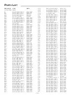
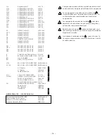
R70

RES 280 OHM 1/10W 1%

RM/10-2800B

R71

RES 10 OHM 1/10W 5%

RM/10-100B

R72

RES 100 OHM 1/4W 5%

RM/4-101C

R73

RES 2.21K OHM 1/10W 1%

RM/10-2211B

R74

RES 2.21K OHM 1/10W 1%

RM/10-2211B

R75

RES 100K OHM 1/10W 5%

RM/10-104B

R76

619K OHM 1/10W 1%

RM/10-6193B

R78

RES 1M OHM 1/10W 5%

RM/10-105B

R79

RES 1M OHM 1/10W 5%

RM/10-105B

R8

POT 2K TRIM

RV-202

R80

RES 6.49K OHM 1/10W 1%

RM/10-6491B

R81

RES 6.49K OHM 1/10W 1%

RM/10-6491B

R82

46.4K OHM RES. 1/10 W 1%

RM/10-4642B

R84

RES 120 OHM 1/10W 5%

RM/10-121B

R85

46.4K OHM RES. 1/10 W 1%

RM/10-4642B

R86

RES 5.49K OHM 1/10W 1%

RM/10-5491B

R87

RES 1.62K OHM 1/4W 1%

RM/4-1621C

R88

RES 2.0K OHM 1/10W 1%

RM/10-2001B

R89

RES 2.21K OHM 1/10W 1%

RM/10-2211B

R9

POT 2K TRIM

RV-202

R90

RES 2.21K OHM 1/10W 1%

RM/10-2211B

R91

RES 9.09KOHM 1/10W 1%

RM/10-9091B

R92

RES 9.09KOHM 1/10W 1%

RM/10-9091B

R93

RES 3.32K OHM 1/10W 1%

RM/10-3321B

R94

RES 2.0K OHM 1/10W 1%

RM/10-2001B

R95

RES 3.24K OHM 1/10W 1%

RM/10-3241B

R96

RES 1.62K OHM 1/4W 1%

RM/4-1621C

R97

RES 1.33K OHM 1/4W 1%

RM/4-1331C

R98

24.9K OHM RES. 1/10 W 1%

RM/10-2492B

R99

RES 1.0K OHM 1/10W 1%

RM/10-1001B

C1

CAP 220PF 50V 5%

CDS-221CAAA

C10

CAP 47PF 50V 5%

CDS-470CAAA

C11

CAP 10UF 16V

CER-106SM

C12

CAP 3300UF 35V

CERS-338B

C14

CAP .47UF 50V

CYV-474-033

C15

CAP .1UF 50V

CYV-104-033

C16

CAP 3300UF 35V

CERS-338B

C17

CAP .1UF 50V 10%

CDS-104CBBB

C18

CAP .1UF 50V 10%

CDS-104CBBB

C19

CAP .1UF 50V 10%

CDS-104CBBB

C2

CAP 220PF 50V 5%

CDS-221CAAA

C20

CAP .1UF 50V 10%

CDS-104CBBB

C202

CAP 100PF 50V 5%

CDS-101CAAA

C21

CAP 47PF 50V 5%

CDS-470CAAA

C22

CAP .47UF 50V

CYV-474-033

C23

CAP .47UF 50V

CYV-474-033

C24

CAP .1UF 50V 10%

CDS-104CBBB

C25

CAP .1UF 50V 10%

CDS-104CBBB

C26

CAP .1UF 50V

CYV-104-033

C27

CAP .1UF 50V 10% 

CDS-104CBBB

C28

CAP 2.2UF 50V

CER-225CSM

C29

CAP 10UF 16V

CER-106SM

C3

CAP .1UF 50V 10%

CDS-104CBBB

C30

CAP .1UF 50V 10%

CDS-104CBBB

C31

CAP .1UF 50V 10%

CDS-104CBBB

C32

CAP 10UF 16V

CER-106SM

C34

CAP .1UF 50V

CYV-104-033

C35

CAP 100PF 50V 5%

CDS-101CAAA

C36

CAP .0022UF 50V

CYV-222-033

C38

CAP 47PF 50V 5%

CDS-470CAAA

C39

CAP 47PF 50V 5%

CDS-470CAAA

C4

CAP .1UF 50V 10%

CDS-104CBBB

C40

CAP .001UF 50V

CYV-102-033

C41

CAP .001UF 50V

CYV-102-033

C42

CAP .001UF 50V

CYV-102-033

C43

CAP .001UF 50V

CYV-102-033

C44

CAP 220PF 50V 5%

CDS-221CAAA

C45

CAP .01UF 50V

CYV-103-033

C46

CAP .01UF 50V

CYV-103-033

C47

CAP .001UF 50V

CYV-102-033

C48

CAP .001UF 50V

CYV-102-033

C49

CAP 220PF 50V 5%

CDS-221CAAA

C5

.047UF 50V

CYV-473-033

C50

CAP .001UF

CDS-102CBAA

C51

.047UF 50V

CYV-473-033

C52

CAP 120PF CDS-121CAAA

C53

CAP .1UF 50V

CYV-104-033

C54

CAP 47PF 50V 5%

CDS-470CAAA

C55

CAP .001UF 50V

CYV-102-033

C56

CAP .001UF 50V

CYV-102-033

C57

CAP .1UF 50V 10%

CDS-104CBBB

C58

CAP .1UF 50V 10%

CDS-104CBBB

C59

CAP 47PF 50V 5%

CDS-470CAAA

C6

CAP 220PF 50V 5% 

CDS-221CAAA

C60

CAP .001UF 50V

CYV-102-033

C61

CAP .001UF 50V

CYV-102-033

C62

CAP-022UF 50V

CYV-223-033

C63

CAP-022UF 50V

CYV-223-033

C64

CAP .0022UF 50V

CYV-222-033

C65

CAP 220PF 50V 5%

CDS-221CAAA

C66

CAP 120PF 50V 5%

CDS-121CAAA

C67

CAP .1UF 50V

CYV-104-033

C69

CAP 47PF 50V 5%

CDS-470CAAA

C7

CAP 220PF 50V 5%

CDS-221CAAA

C70

CAP 10UF 16V

CER-106SM

C71

CAP 3300UF 35V

CERS-338B

C72

CAP 3300UF 35V

CERS-338B

C75

CAP 47PF 50V 5%

CDS-470CAAA

C76

CAP .47UF 50V

CYV-474-033

C80

CAP .1UF 50V 10%

CDS-104CBBB

C81

CAP .1UF 50V 10%

CDS-104CBBB

C82

CAP .1UF 50V 10%

CDS-104CBBB

C83

CAP 47PF 50V 5%

CDS-470CAAA

C84

CAP .1UF 50V 10%

CDS-104CBBB

C85

CAP .1UF 50V

CYV-104-033

C86

CAP 220PF 50V 5%

CDS-221CAAA

C87

CAP 120PF 50V 5%

CDS-121CAAA

C88

CAP 120PF 50V 5%

CDS-121CAAA

C9

CAP .1UF 50V 10%

CDS-104CBBB

CR1

DIO DUAL BAV99L

SS-260SM

CR10

BRIDGE RECTIFIER

SS-0799-068

CR11

DIO DUAL BAV99L

SS-260SM

CR13

DIO MMBD914L

SS-803SM

CR14

DIO ZENER MMBZ5240BL

SS-1052

CR15

DIO DUAL BAV99L

SS-260SM

CR16

DIO DUAL BAV99L

SS-260SM

CR2

DIO DUAL BAV99L

SS-260SM

CR22

DIO MMBD914L

SS-803SM

CR3

RD/GRN BICOLOR LED

SS-2423

CR4

DIO DUAL BAV99L

SS-260SM

CR5

DIO MMBD914L

SS-803SM

CR6

DIO MMBD914L

SS-803SM

CR7

DIO MMBD914L

SS-803SM

CR8

DIO MMBD914L

SS-803SM

CR9

DIO DUAL BAV99L

SS-260SM

Q10

XSTR MMBT3906LT1 PNP

SS-0791

Q11

XSTR MMBT5088L NPN

SS-0114

Q12

XSTR MMBT5088L NPN

SS-0114

Q13

XSTR MPS-A56

SS-101A-45

Q14

XSTR MMBT5088L NPN

SS-0114

Q15

XSTR NPN MPSA06

SS-102A-45

Q16

XSTR MMBT5088L NPN

SS-0114

Q17

XSTR MMBT5088L NPN

SS-0114

Q18

XSTR MMBT5087L PNP

SS-0115

Q19

XSTR MMBT3906LT1 PNP

SS-0791

Q2

Regulator LM317

SS-1375

Q21

XSTR MMBTA06L

SS-102SM

Q22

XSTR MPS-A56R

SS-101A-45

Q23

XSTR NPN MPSA06

SS-102A-45

Q24

XSTR MMBT3904LT1 NPN

SS-0792

Q25

XSTR MMBT5088L NPN

SS-0114

Q26

XSTR MMBT5087L PNP

SS-0115

Q27

XSTR MMBT5088L NPN

SS-0114

Q28

XSTR MMBT5088L NPN

SS-0114

Q29

XSTR MPS6521

SS-209

Summary of Contents for TRM6.1

Page 1: ......

Page 2: ...S A Importer s Name ________________________________________________________ Importer s Address ________________________________________________________ Type of Equipment 2 channel Audio Power Amplif...

Page 3: ...TC 20Hz 20kHz 0 1 THD 35 Watts RMS 6 ohms high frequency 50 Watts RMS 4 ohms low frequency Signal to Noise 100dB CMRR 70dB typical 1kHz Input Impedance 47k per phase balanced 47k unbalanced Input Sens...

Page 4: ...f the equip ment s plug be able to fully insert into the mating receptacle Never remove the round grounding pin on the plug in an attempt to mate to a two wire ungrounded receptacle use a grounding ad...

Page 5: ...rioente requerida pra la operaci n segura de todo el equipo conectado Aun m s las extensiones deben proveer de la misma conecci n aterrada de tres hiles Es importante que el enchufe se pueda introduci...

Page 6: ...rt des util isations de ce mat riel L utilisation de rallonge t d adaptateur est d consell e moins d tre en mesure de fournir la charge lectrique requise un fonctionement sans risque de tout mat riel...

Page 7: ...isten Anwendungen v l lig ausreicht Wenn Sie Verl ngerungskabel benutzen achten Sie darauf das dies die erforderlichen Str me bertragen k nnen Benutzen Sie immer dreiadrige Verl ngerungskable 11 ZEITR...

Page 8: ...i impieghi L impiego di prolunghe e adattatori sconsigliato se questi non garantiscono la potenza sufficiente per i corretto fuinzionamento degli apparati connessi E alters importante che vengano semp...

Page 9: ...matic Diagram 7 PC Board Layout 12 OPERATION Input Sensitivity 13 Bass Roll Off 13 Bass Shelving 14 Treble Shelving 14 AC Line 14 Power Switch 14 Status LED 15 Rubber Pad 15 Break In and Warm Up 15 Cl...

Page 10: ...r The high frequency channel features up to 4dB of Treble shelving while the low frequency channel features up to 4dB of Bass shelving In addition the low frequency channel includes an active 2nd orde...

Page 11: ...y an active node formed by the driver transistors at ultrasonic frequencies This allows amplifier performance similar to Trans nova which is highly stable and linear while utilizing the advantages of...

Page 12: ...his type of shielding prevents color and image distortion when placing the woofer in close proximity to direct view CRT television receivers and computer monitors THE RESULT Prevents distortion in TV...

Page 13: ...nt Panel View 4 Rear Panel View Woofer Tweeter Rubber Pad Status LED Wave Guide Heatsink AC Line Input AC Line Fuse Balanced Input Unbalanced Input Sensitivity Bass Roll Off Bass Shelving Treble Shelv...

Page 14: ...TION Aiming the monitors directly forward Fig 1 may cause response problems resulting in inadequate stereo imaging Aiming the monitors toward you and spaced equally like a triangle Fig 2 provides the...

Page 15: ...noise INPUT SWITCH The unbalanced input uses a conventional RCA phone jack Move the input switch ON to use this jack The balanced input jack is an XLR plug The XLR jack is connected according to the I...

Page 16: ...SCHEMATIC DIAGRAM NOTES Unless specified otherwise 1 All resistors in ohms 2 All capacitors in microfarads 3 Channel 1 only shown 7...

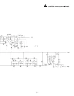
Page 17: ...Qualified Service Personnel Only 8...

Page 18: ...SCHEMATIC DIAGRAM NOTES Unless specified otherwise 1 All resistors in ohms 2 All capacitors in microfarads 3 Channel 1 only shown 9...

Page 19: ...Qualified Service Personnel Only 10...

Page 20: ...11 S CHEMATIC Diagram NOTES Unless specified otherwise 1 All resistors in ohms 2 All capacitors in microfarads 3 Channel 1 only shown Qualified Service Personnel Only...

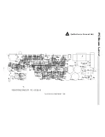
Page 21: ...PC B OARD L AYOUT Qualified Service Personnel Only 12...

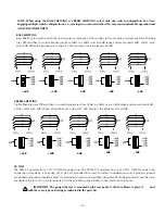
Page 22: ...Y select only one switch configuration at a time Engaging multiple switch configurations i e moving two or more switches ON may cause undesirable operation and is NOT RECOMMENDED I N P U T 11dB Input...

Page 23: ...equencies from 5kHz to 20kHz over an 8dB range and are marked 4dB 2dB 2dB and 4dB When all switches are in the OFF left position the treble level is at 0dB 14 2dB 4dB 2dB 0dB 4dB 2dB 4dB 2dB 0dB 4dB A...

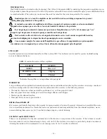
Page 24: ...ED Amplifier operation is monitored internally and has a status LED This indicator can be used for system troubleshooting in case of aberrant behavior RUBBER PAD A large rubber pad is supplied to elim...

Page 25: ...1 10W 1 RM 10 2001B R172 RES 2 0K OHM 1 10W 1 RM 10 2001B R173 RES 2 21K OHM 1 10W 1 RM 10 2211B R174 RES 1 33K OHM 1 4W 1 RM 4 1331C R175 35 7K OHM 1 10 WATT 1 RM 10 3572B R176 RES 909 OHM 1 10W 1 RM...

Page 26: ...C44 CAP 220PF 50V 5 CDS 221CAAA C45 CAP 01UF 50V CYV 103 033 C46 CAP 01UF 50V CYV 103 033 C47 CAP 001UF 50V CYV 102 033 C48 CAP 001UF 50V CYV 102 033 C49 CAP 220PF 50V 5 CDS 221CAAA C5 047UF 50V CYV 4...

Page 27: ...T3906LT1 PNP SS 0791 Q7 XSTR MMBT3906LT1 PNP SS 0791 Q8 XSTR MMBT3904LT1 NPN SS 0792 U1 OPAMP TL072CD SS 143SM U112 OPAMP TL072CD SS 143SM U2 OPAMP TL072CD SS 143SM U3 OPAMP TL072CD SS 143SM U4 OPAMP...

Page 28: ...TRM6 1 FUNCTIONAL BLOCK DIAGRAM 19...

Page 29: ...nt end drive current and drive the positive output MOSFET Q20 The same is true for buffer transistors Q31 and Q33 and negative output MOSFET Q4 CALIBRATION WARNING Only a competent technician should a...

Page 30: ...gnal from U1A pin 1 and the inverting input signal from U1B pin 7 are summed together to form an unbalanced signal at U4A pin 1 Input Circuit Tweeter Crossover The balanced input signal at U1A pin 1 a...

Page 31: ...w pass filter at U2A which cascades with the previous filter at U112B to produce an overall 4th order slope of 24dB octave for the woofer amplifier Thermal Protection The thermal protection is activat...

Page 32: ...pin 9 of U5D Excessive drive sig nal at pin 6 or pin 8 will trigger its comparator low and light the CLIP THERMAL indicator red On Indicator The bicolor LED CR3 will remain green unless a THERMAL or C...

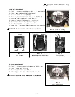
Page 33: ...e replacement tweeter into wave guide 8 Snap the tweeter into wave guide 9 Follow steps 1 5 in reverse order to install wave guide assembly CAUTION Reconnect wires as indicated in each diagram Wave Gu...

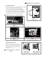
Page 34: ...connect PCB mounted power switch wires FIG 8 CAUTION Reconnect wires as indicated in diagram FIG 5 Amplifier Replacement Remove only these 2 screws FIG 6 PCB Mounted LED Harness FIG 7 PCB Mounted Spea...

Page 35: ...than Hafler or an Authorized Hafler service center 3 Any product purchased outside the United States please contact your local dealer 4 Shipping charges to get the unit to Hafler 5 Any product which...

Page 36: ...This product is designed developed and assembled in the USA by a dedicated group of American workers The majority of the components used in the con struction of this product are produced by American...

Reviews: