background image

CI-1255e™ Power Amplifi er

Hafl er

Passion for Perfection

5

CoNNeCTING The PoWeR

Your Hafl er amplifi er has been factory set for use in your country. If you are in the United States or Canada or other countries that 

employ 110-120 volts, the rear panel voltage switch will be factory set to 115 volts. If you are in Europe, the United Kingdom, Australia 

or other countries that employ 220-240 volts, the rear panel voltage switch will be factory set to 230 volts. The CI-1255e is designed to 

safely handle a fairly wide voltage range at the input to address most needs. It is a good idea to check the voltage just in case it has not 

be set properly. The voltage should clearly appear in the window. If not correct, you can change it by removing the protective window 

using a hex screwdriver and set it as needed. It is a good idea that you have a qualifi ed service technician verify this on your behalf. 

Your Hafl er CI-1255e comes with a standard IEC 3-prong plug with an integral safety ground. This is there to protect you should the 

electrical system develop a fault. It is both illegal and extremely dangerous to remove the third safety ground. This is sometimes done 

in order to try to reduce system noise. If you encounter noise, the most effective method of reducing it is to insert the Hafl er CI9012, 

CI9022 or CI9024 balancing/isolating modules into the Omniport, or by inserting a Jensen Iso-Max CI-2RR onto any of the offending 

channels. These are easily installed in series at the input of the amplifi er and provide an effective and safe means of eliminating 

system noise.

Connecting the speaker cable from the CI-1255e is done using 

a series of detachable euro-block (Phoenix style) connectors. 

These snap in and out of place for a secure lock and the 

wire is inserted and the screwed down into place using a 

fl at-blade screwdriver or tweaker. Disconnect the euro-block 

connectors from the amp to connect the speaker wires and 

then reconnect once all the zones have been determined. 

CoNNeCTING The SPeAkeRS

Before  making  connections,  ensure  the  amplifi er  is  turned  off  along  with  all  of  the  source 

equipment. This will avoid loud plug in and connection transients that can damage more 

sensitive components such as tweeters. 

It is also very important that you do not connect loudspeakers that are below the designated 

impedance. Your Hafl er CI-1255e is capable of driving loads down to 4 ohms, but not less. 

Driving loads below the rated impedance can lead to overheating and premature part failure.  

For greater effi ciency, you should also use suffi ciently large speaker cable gauge that correlates 

to the length of cable in use. Proper speaker wire selection will also improve the performance 

of the amplifi er and resulting sound. The following table has been prepared as a reference:

Recommended speaker wire (core size)

DISTANCE

IMPERIAL (gauge)

DISTANCE

METRIC (Conductor OD)

25 feet

18 AWG

8 meters

1.02 mm

50 feet

16 AWG

15 meters

1.29 mm

100 feet

14 AWG

30 meters

1.63 mm

150 feet

12 AWG

45 meters

2.05 mm

200 feet

10 AWG

60 meters

2.59 mm

ImPoRTANT NoTe 

Your loudspeakers should be able to handle a minimum of 100 Watts peak (60 watts RMS) to ensure that the CI-1255e does not 

damage them if driven hard. 

+

+

1L 2R

SPEAKERS

Summary of Contents for CI-1255e

Page 1: ...CI 1255e User Guide 12 Channel Multi Zone Power Amplifier Hafler is a division of Radial Engineering Ltd 1588 Kebet Way Port Coquitlam BC Canada V3C 5M5 604 942 1001 info hafler com www hafler com ...

Page 2: ......

Page 3: ... experienced professionals it is in fact easy to use It is important to note that the design features a number of functions that are worthy of your full understanding So before you start connecting wires please take some time to read through this short manual After you have done your homework if you find yourself asking questions please visit the Hafler FAQ page This is where we post questions fro...

Page 4: ...ng in a 19 rack ensure at least a single rack space is provided above and below the amplifier to assure proper ventilation 8 Do not ever cut or cheat the 3rd safety prong it is there for your safety 9 Protect the power cord from being walked on or pinched particularly at plugs convenience receptacles and the point where they exit from the apparatus 10 Only use attachments and or accessories specif...

Page 5: ...many of the stereo pairs as you like The CI 1255e is turned on and off via the front panel power switch and with ECOSYSTEM it automatically turns itself off when no signal is present for energy savings The CI 1255e will automatically spring back to life in 10 milliseconds as soon as signal is detected The front panel also has a power present indicator and an ECOSYSTEM indicator that illuminates wh...

Page 6: ... extra durability 4 PoWeR Led Lets you know the CI 1255e is powered up and working 5 eCoSySTem Power saving feature automatically sets the amplifier on standby when audio signal is inactive for over a minute Automatically comes to life in 10 milliseconds as soon as signal is detected on any channel 6 eNCLoSuRe Compact 17 x 3 5 x 11 5 432 x 89 x 292mm solid steel enclosure 7 RACk eARS Optional rack...

Page 7: ...ts signal presence rear mounted to simplify setup when configuring and testing system 14 SPeAkeR Euroblock Phoenix style detachable screw down connectors for quick easy and reliable connectivity to the loudspeaker wires Handles 18 to 10 gauge wire 15 omNIPoRT module input slot expands connectivity with optional Dante digital network card unbalanced Euroblock input connectors transformer isolation ...

Page 8: ...ant if rack mounting more than one amplifier in your rack If being used this way you can remove the large feet using a Philips 2 screwdriver Be sure to use the rack ear hardware supplied with the kit Longer mount screws may contact internal parts that may cause critical safety violations HIGH CURRENT AMPLIFIER 12 X 55 WATTS 2 3 4 5 6 7 8 9 10 11 12 CLIP SIGNAL CI 1255e POWER 1 BUS IN Hafler TM OPE...

Page 9: ...d provide an effective and safe means of eliminating system noise Connecting the speaker cable from the CI 1255e is done using a series of detachable euro block Phoenix style connectors These snap in and out of place for a secure lock and the wire is inserted and the screwed down into place using a flat blade screwdriver or tweaker Disconnect the euro block connectors from the amp to connect the s...

Page 10: ... the source and the bridged amplifier When connecting the cable make sure you connect the speaker using the two OUTSIDE terminals You should also increase the wire gauge size to compensate for the extra power as this will reduce the loss due to heat dissipation in the cable The minimum subwoofer impedance is 8 ohms CoNNeCTING The INPuTS There are several ways to connect to the CI 1255e from your s...

Page 11: ...have as many or as little channels connected to the bus and these do not have to be in any particular order Simply activate to suit your setup requirements A handy 3 5mm TRS input on the front panel allows you to connect audio from a laptop tablet phone or even a Bluetooth adaptor The front panel 3 5mm input is in parallel with the rear panel BUS RCA inputs Do not attempt to use both at the same t...

Page 12: ...n the out position You can also mix and match by having some of the channels fed by the bus and others fed by individual source programs A common application could be a hotel lobby and bar whereby you may want to have the lobby supplied with gentle background classical music while the bar would be fed some rock and roll Zone 6 Bridge Mono Zone 1 Zone 2 Zone 5 Zone 4 Zone 3 Rock Playlist Classical ...

Page 13: ...ing a cell phone or tablet as a source during setup is made easy with the 3 5mm front panel input Start with the trim controls fully open fully clockwise and your preamp turned down Turn on the source material and the amplifier check the LEDs to make sure signal is being received and turn up the preamp until the desired level is achieved If any of the zones are too loud you can use a tweaker or a ...

Page 14: ...nge the cables one at a time to determine if one or all cables are responsible If the hum disappears when the input cables are disconnected but returns after the cables are changed and the system reconnected your source device may be causing the problem Try the same process by replacing the cables one at a time to see if you can locate a problem Starting Backwards If after testing your cables you ...

Page 15: ...instead powered by a distant cable TV sub station With two power sources it is easy to understand how this can pose a problem To determine if a cable TV connection is responsible for the hum first turn off all the components Disconnect the cable TV feed to your system Turn your system back on and listen if the hum has disappeared If removing the cable TV feed has eliminated the hum you will need t...

Page 16: ...er cable is connected 2 Make sure the power switch is pushed in in the ON position 3 Check the signal present LEDs to make sure source signal is being received Speakers pops when amp turns on or off 1 The speakers may need a resistor placed across the amp terminal 2 We suggest 2k0 W resister 3 This will discharge the speaker output s internal capacitor Speakers sound as if lacking bass 1 Out of ph...

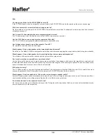
Page 17: ...that is rated higher than the recommended impedance The efficiency of the system will be reduced and the system will not play as loud Can I stack more than one amplifier on top of each other Yes but this must be done in such a way to ensure proper ventilation If stacked on a shelf ensure the large feet are employed and that the sides and back are free from obstructions If you are rack mounting the...

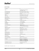
Page 18: ...20Hz to 20kHz IMD Distortion 0 01 60Hz Common Mode Rejection 70dB direct coupled 90dB with Jensen transformer option Dimensions 17 x 3 5 x 11 5 432 x 89 x 292mm HushTone Fan Noise 22dB maximum Power Maximum 750 watts at 117VAC or 230VAC Gain control 40dB to 20dB for each channel Weight 24lbs 11kg Storage Temperature 40 to 120 C Working Temperature 5 to 40 C Voltage Requirements 115V 60 Hz 230V 50H...

Page 19: ... RIGHT 1 LEFT 2 RIGHT L R L R PROCESS ECO DETECT LEFT LEFT RIGHT RIGHT 3 LEFT 4 RIGHT L R L R PROCESS ECO DETECT LEFT LEFT RIGHT RIGHT 5 LEFT 6 RIGHT L R L R PROCESS ECO DETECT LEFT LEFT RIGHT RIGHT 7 LEFT 8 RIGHT L R L R PROCESS ECO DETECT LEFT LEFT RIGHT RIGHT 9 LEFT 10 RIGHT L R L R PROCESS ECO DETECT LEFT LEFT RIGHT RIGHT 11 LEFT 12 RIGHT L R L R BUS INPUT 3 5mm or REAR RCA s L R Ci1255e BLOCK...

Page 20: ...warranty period expires The product must be returned prepaid in the original shipping container or equivalent to Hafler or to an authorized Hafler repair centre and you must assume the risk of loss or damage A copy of the original invoice showing date of purchase and the dealer name must accompany any request for work to be performed under this limited and transferable warranty This warranty shall n...

Reviews: