11
A Fig.5
C Fig.6 B
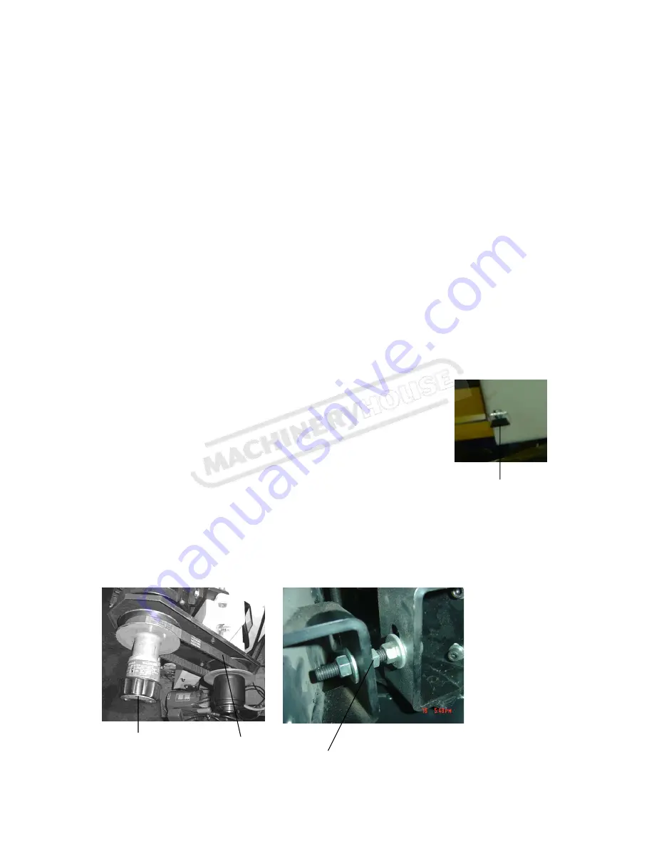
A Fig.4
7.
When discontinued cutting or reset cutting is necessary during operation,close the cylinder feeding
valve,then push the stop button(F)
8.
Press emergency button(E) to shut-off the motor when in emergent situation Before next operation
release (E) to get power.
9. AS the operator locate the working piece in the vise, turn the laser light on (F), the laser will mark on the
work piece for cutting reference.
10.Turn (H) to controlling downwards of saw arm. And control the downward speed by adjusting
hydraulic volume valve.
11.An automatic shut-off limit switch is provided to stop the motor when the cut is completed. The limit
switch (K) is controlled by button (L)(figure 3), which contacts the rear cylinder (M) for shutting off the
motor and coolant system.
Notice:
1, Before start blade running, operator has to ensure the blade is assembled appropriately, the blade
cover is closed, and the emergency bottom is on. After the confirmation, the machine can be operated
only.
2, After the cutting is completed, make sure the main power is cut-off for safety.
**Usage of laser light: AS the operator locate the working piece in the vise, turn the laser light on (F),
the laser will mark on the work piece for cutting reference.
Notice: Laser light is for cutting reference only, operator can turn it off during the cutting for longer life
of the laser light.
9-3.ADJUSTING DOWNWARD TRAVEL OF SAW ARM
The downward travel of the saw arm should be adjusted so that when the saw
arm is in the extreme downward position, the teeth of the blade will not touch
the table surface. The stop screw (A) (Fig.4) is used to adjust the distance
between blade and table surface. After the distance is adjusted, tighten lock nut.
9-4.CHANGING SPEEDS AND ADJUSTING BELT TENSION
If the belt (B) (Fig 6) is too loose, Loosen screw nut (A)(Fig5) adjust the screw to
proper tension and lock the screw nut.
The cutting speed is controlled by speed change C (Fig 6). Turn it clockwise to decrease the cutting speed
and increase the cutting speed by turning counter-clockwise.
Change speed always when motor is running, and be sure the belt cover is always in locked position.
13
Instruction Manual for BS-13LS (B031)
30/03/2016
Summary of Contents for BS-13LS
Page 21: ...19 12 CIRCUIT DIAGRAM 21 Instruction Manual for BS 13LS B031 30 03 2016 ...
Page 22: ...20 22 Instruction Manual for BS 13LS B031 30 03 2016 ...
Page 23: ...16 PARTS LISTS 21 23 Instruction Manual for BS 13LS B031 30 03 2016 ...
Page 24: ...22 24 Instruction Manual for BS 13LS B031 30 03 2016 ...
Page 25: ...23 25 Instruction Manual for BS 13LS B031 30 03 2016 ...


