background image

6

C. MAIN SPECIFICATIONS

MACHINE

MODEL

AL-320

Centre Height

160mm

Max. swing over bed

320mm

Max. length of work piece

600/750mm

Max. swing over cross slide

170mm

Headstock taper

MT5

Spindle bore

38mm

Spindle speed steps

6/12

Spindle speed range

60/1600 r.p.m.

TOOLPOST

Max. Cross slide travel

200mm

Max. Top slide travel

100mm

TAILSTOCK

Max barrel travel

80mm

Tailstock taper

MT3

THREADS

No. Metric threads

15

No. Inch threads

23

Range of metric threads

0.5-4mm

Range of inch threads

9-48 Threads / Inch

MOTOR

Motor power

750 watts

Voltage

240Volt

Frequency

50Hz

DIMENSIONS

Unit packing (LxWxH) cm.

137x70x66

WEIGHT

Net weight

220kgs

Page 6

Instructions Manual for AL-320G (L141)

07/02/2018

Summary of Contents for AL-320G

Page 1: ...1 Metal Cutting Lathe OPERATION MANUAL Model AL 320G Page 1 Instructions Manual for AL 320G L141 07 02 2018 ...

Page 2: ...ERIAL NO DATE OF MANF NOTE This manual is only for your reference Owing to the continuous improvement of the ma chine changes may be made at any time without obligation or notice Please ensure the local voltage is the same as listed on the specification plate before operating this electric machine Distributed by www machineryhouse co nz MACHINE DETAILS Page 2 Instructions Manual for AL 320G L141 0...

Page 3: ...d Adjustment Of The Lathe 12 E 1 Installation 12 E 2 Adjustment Of The Lathe 13 E 2 1 Adjustment Of Main Spindle 13 E 2 2 Adjustment Of Clearance Between The Top Slide Worktable And Cross Slide 13 E 2 3 The Adjustment Of The Locking Handles Of TheTailstock 14 F Operation 15 F 1 Illustration Of The Operation Parts 15 F 2 Speed Changing Of The Main Spindle 16 G Lubrication 16 Lubrication Points 17 T...

Page 4: ... the machine 6 Ensure correct speed for machining process is selected 7 Remove the chuck key before starting the lathe 8 Do not try to lift chucks or face plates that are too heavy for you 9 The lathe should not be used if faulty Safety Checks While Operating 1 Never leave the lathe running unattended 2 Before making adjustments or measurements switch off and bring the machine to a complete stop 3...

Page 5: ...eding Box 16 Longitudinal Leadscrew 17 Longitudinal Feeding Hand Wheel 18 Cross Feed Handle 19 Apron 20 Half nut Lever 21 Handle for Longitudinal cross Feeds 22 Bed B MAIN USAGE AND FEATURES The machine is used mainly for the turning drilling threading reaming and knurling of metal work pieces The machine has excellent features with easy operation It is suitable for use in small enter prises repai...

Page 6: ...ange 60 1600 r p m TOOLPOST Max Cross slide travel 200mm Max Top slide travel 100mm TAILSTOCK Max barrel travel 80mm Tailstock taper MT3 THREADS No Metric threads 15 No Inch threads 23 Range of metric threads 0 5 4mm Range of inch threads 9 48 Threads Inch MOTOR Motor power 750 watts Voltage 240Volt Frequency 50Hz DIMENSIONS Unit packing LxWxH cm 137x70x66 WEIGHT Net weight 220kgs Page 6 Instructi...

Page 7: ...Slide Lead Screw 17 Top Slide Lead Screw Nut 18 Tailstock Lead Screw 19 Tailstock Lead Screw Nut 20 Longitudinal Lead Screw 21 Half nut for Longitudinal Lead Screw 22 Cross Slide Lead Screw 23 Cross Slide Lead Screw Nut 24 Gears 25 Gears 26 Gears 27 Worm Gears 28 Worm 29 Gears 30 Gears 31 Gears 32 Gears 33 Gears 34 Sliding Gears 35 Gears 36 Motor Pulley 37 Input Shaft 38 Middle Shaft 39 Output Sha...

Page 8: ... to stop the rotation of the lead screw shaft This lever should not be changed while the spindle is running To engage the auto feed use the handle on the carriage It has three positions 1 neutral no feed engagement 2 feed to the cross slide or 3 feed to the longitudinal travel Fig 2 The machine feed gears are factory set to A 24 B 50 C 25 D 48 producing 0 100mm per rev olution longitudinal travel ...

Page 9: ...f nut is engaged the longitudinal and cross feeds are inter locked and will only allow one option to operate The direction of the threading can be achieved by switching the direction change shift on the feeding box Fig 3 D 2 2 Threading Half Nut Lever Fig 5 Change Gears To make changes to the gear train remove the clips loosen the T bolt and locking nut on the pack Change the necessary gears repla...

Page 10: ...10 Thread Chart Page 10 Instructions Manual for AL 320G L141 07 02 2018 ...

Page 11: ...re over the cross slide and use a fine ruler to measure the distance from the surface of the cross slide to the tip of the centre Adjust the cutting tool height so it is the same distance above the cross slide as the tailstock centre Align the tip of the cutting tool with a tail stock centre as described in the following procedure 1 Mount the cutting tool and secure the post so the tool faces the ...

Page 12: ...oid any damage To keep the lathe in balance the carriage and the tailstock should be moved away from the headstock to the opposite end of the bed It is important to ensure that the tailstock is clamped in order to avoid moving or falling off the end of the bed Fig 6 Fig 6 Place the lathe on the Stand using the four recommended bolts to secure the lathe on the Stand The Stand is an optional accesso...

Page 13: ...ing the factory If any adjustment is required please make the change by adjusting the wedges and nuts as per the instructions shown in the picture below The clearance is very important for the accuracy of the lathe Ensure that the adjustment is not too tight as this could cause the slideway to wear unevenly making it difficult for the carriage to move If there is too much clearance in the slides t...

Page 14: ...f The Locking Handles Of The Tailstock The locking of the tailstock can be achieved by either the locking nut or locking handle Ad justing the stroke of locking handle can be achieved by adjustment of the nuts Fig 13 Locking Handle Locking Nut Adjusting Nut Fig 13 Page 14 Instructions Manual for AL 320G L141 07 02 2018 ...

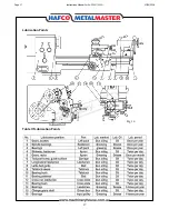
Page 15: ... stopped 7 Start button to start the motor 8 Stop button to stop the motor 9 Longitudinal hand wheel to operate the apron longitudinal movement 10 Cross hand wheel to move the cross slide and toolpost 11 Toolpost handle for loosing or locking the toolpost 12 Nuts to fix the top slide to the cross slide This can allow rotation on the topslide 14 Toolpost hand wheel to move the topslide and toolpost...

Page 16: ...g lubrication for other points To change the headstock oil remove the oil and clean the inside of the headstock with a clean cloth Then fill with clean lubricating oil After the machining operation is finished the surfaces of the slideways must be cleaned and the swarf removed The slides should then be covered with oil a Recommend to use Grease 3 as listed in table of lubrication positions Fig 17 ...

Page 17: ...17 Lubrication Points Table Of Lubrication Points Fig 16 Page 17 Instructions Manual for AL 320G L141 07 02 2018 ...

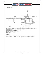
Page 18: ...cian Wiring Colour Code Yellow Green wire Grounding Blue wire Neutral Brown Live Cautions If the motor does not work while the power voltage is on first check the cut out units E G check if the micro switch has been closed properly inside the change gear box Page 18 Instructions Manual for AL 320G L141 07 02 2018 ...

Page 19: ...r parts list diagram with required spare part s identified 3 Go to www machineryhouse com au contactus and fill out the enquiry form attaching a copy of scanned parts list CONTENTS AL 320 Bed Parts 20 AL 320 Bed Parts List 21 AL 320 Headstock Parts 23 AL 320 Headstock Parts List 24 AL 320 Back Gear Parts 27 AL 320 Back Gear Parts List 28 AL 320 Gearbox Parts 30 AL 320 Gearbox Parts List 31 AL 320 ...

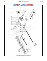
Page 20: ...20 AL 320 BED PARTS Page 20 Instructions Manual for AL 320G L141 07 02 2018 ...

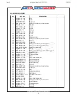
Page 21: ... 138 12x40 GB4141 9 84 M1 GB923 88 CQ9332 05 008 M8x40 GB70 85 CQ9332 01 007 CQ9332 5 005 CQ9332 05 002 6 GB1155 79 Bed Racks Taper pin Hexagon socket cap head screws Washer Screw Chuck Oil cup Washer Screw Screw Hexagon nuts Hexagon socket cap head screws Oil cup Taper pin Hexagon socket cap head screws Hexagon socket cap head screws Hexagon head bolts Chuck Hexagon socket set screws with dog poi...

Page 22: ...4 10 GB93 87 M10x40 GB70 86 M10x35 GB70 85 CQ9332 00 016 M5x10 GB70 85 Cross nut Middle carriage Shield Longitudinal feed screw Right pedestal Oil cup Sleeve Spigots Hexagon socket cap head screws Taper pin Slotted set screws with cone point Taper pin Coupling sleeve Washer Hexagon socket cap head screws Hexagon socket cap head screws Shield Hexagon socket cap head screws AL 320 BED PARTS LIST Con...

Page 23: ...23 AL 320 HEADSTOCK PARTS Page 23 Instructions Manual for AL 320G L141 07 02 2018 ...

Page 24: ... CQ9332 02 006 68 JB GQ0324 89 AT400 04 123 M5 x20 GB70 85 CQ9332 02 004 20 GB894 1 86 CQ9332 02 023 Spanner nut Lock washer for circular nut Plain washers Plain parallel key Spindle pulley Taper roller bearing Hexagon socket head serew Pulley seat Felt collar Circlips for shaft type A Single row ball bearing Lathe head Pressurize Washer Transmission cover Hexagon socket head screw Rubber ring Oil...

Page 25: ...332 02 038 CQ9332 02 033 CQ9332 02 034 16x2 4 GB1235 76 AT400 04 127 M5x 12 GB819 85 6 5 GB308 84 0 8x5x25 GB2089 80 5x50 GB117 86 BM8x40 GB4 4l 14 84 BM8x63 GB4 4l 15 84 12x50 GB4141 19 84 Plain paralle key External snap ring Gear Plain paralle key Middle shaft Single row ball bearing Bearing sleeve Right sleeve Screw Screw Output shaft Gear Gear Gear Plain paralle key Sleeve spacer Single row ba...

Page 26: ...5 200 7 1 IO GB297 84 CQ9332 02 044 CQ9332 02 043 50 JB GQ0324 89 AT400 04 118 M5x320 GB70 85 50 GB858 88 M50 GB812 88 Pin Spring Steel ball Screw Locating sleeve 0 seal ring Left shifting fork shaft Left shifting fork Single row ball bearing Pressurize washer Felt collar Left sleeve Screw Gear Plain parallel key Spring washer Hexagon nut Single row ball bearing Pressurize washer Sleeve Screw Tape...

Page 27: ...27 AL 320 BACK GEARS PARTS Page 27 Instructions Manual for AL 320G L141 07 02 2018 ...

Page 28: ... 145 AT400 03 l42 12 GB97 2 85 9 GB896 86 AT400 04 108 AT400 04 112 AT400A 04 109 AT400 04 110 CQ9332 00 015 12 GB97 2 85 9 GB896 86 6 GB1155 79 Slotted cheesehead screws Spring washers Hexagon nuts Butt hinge Door V belt type 710 Motor pulley Screws Heragon head bolts Spring washers Washer Motor mount plate Compound box 220V Motor 50 HZ Sleeve Slalionary shaft Change gear plate Washer Hexagon nut...

Page 29: ...6 10 GB96 85 AT300 05 108 6 GB896 86 AT300 05 110 AT300 05 111 8x32 GB4141 29 84 3x18 GB117 86 Washer Spring washers Hexagon socket head screw Sleeves Spring washers Heragon head bolts Washer Door knob E rings Shaft Slationary sleeve Star grip knob Taper pins AL 320 BACK GEARS LIST Cont Page 29 Instructions Manual for AL 320G L141 07 02 2018 ...

Page 30: ...30 AL 320 GEARBOX PARTS Page 30 Instructions Manual for AL 320G L141 07 02 2018 ...

Page 31: ... 14 84 BM8x40 GB4141 15 84 12x50 GB4141 19 84 5x50 GB117 86 AT520 03 117 CQ9332 04 003 AT300 03 134 M5x10 GB68 85 6 5 GB308 84 0 8x5x25 GB2089 84 CQ9332 00 003 M4x8 GB8l8 85 Transmission cover Screws Oil cup Set screws with cone point Shaft Plain paralle key Gear Sieeve spacer Sleeves Spigots Shaft Plain parallel key Gear Sieeve spacer Gear Sieeve spacer Sleeves Spigots Transmission cover Screws E...

Page 32: ...32 04 018 CQ9332 04 012 CQ9332 04 019 CQ9332 04 011 M5x12 GB70 85 CQ9332 04 012 CQ9332 04 006 Washer Hexagon socket head screw Left trestle Sieeves Spigots Sieeves Pedestal Hexagon socket head screw Spigots Sieeves AL 320 FEED BOX PARTS LIST Cont Page 32 Instructions Manual for AL 320G L141 07 02 2018 ...

Page 33: ...33 AL 320 APRON PARTS Page 33 Instructions Manual for AL 320G L141 07 02 2018 ...

Page 34: ...B75 85 AT400A 03 212 5x50 08117 86 AT400A 03 221 M4x12 GB68 85 BM8x40 GB4141 14 84 BM8x40 GB4141 15 84 12x50 GB4141 19 84 0 8x5x25 GB2089 80 Plain parallel key Gear shaft Sleeve Screws Set screws with cone point Worm gear Gear Set screws with cone point Spring washer Big gear Extermal snap ring Slippage gear Slippage shaft Apron body Set screws with cone point Set screws with cone point Hexagon so...

Page 35: ...32 05 011 CQ9332 05 022 4x28 JB GQ0217 89 8106 GB301 84 M5x16 GB70 85 CQ9332 05 023 8106 GB301 84 30 GB858 88 M30x 1 5 GB812 88 CQ9332 00 105 M5x8 GB71 85 Steel ball Flat point set serew Spring Steel ball Shifting fork Plain parallel key Shifting fork shaft Sleeve Chuck Screw nut Column pins Hexagon socket head screw Spring washer Set screws with cone point Sleeve Middle gear Shaft Bearing sleeve ...

Page 36: ...36 AL 320 COMPOUND SLIDE PARTS Page 36 Instructions Manual for AL 320G L141 07 02 2018 ...

Page 37: ...0 03 101 AT300 03 138 AT300 03 139 M10x1 GB812 88 3x16 GB117 86 8x25 GB4141 10 84 M6x25 GB75 85 M6 GB6170 86 M6x20 GB75 85 CQ9332 08 007 2x5 GB827 86 CQ9332 08 016 Bolts for T Slot Small carriage Plain washers Hexagon nuts Bolts for T Slot Tollpost seats Spring Locating sleeve Toolpost Screws Plain washers Handle seats Handle lever Long sleeve knobs Nut Lead screw Plain parallel key Hanger Oil cup...

Page 38: ...38 AL 320 TAILSTOCK PARTS Page 38 Instructions Manual for AL 320G L141 07 02 2018 ...

Page 39: ... M5x12 GB75 85 CQ9332 03 006 CQ9332 03 002 CQ9332 03 004 M12 x1 5 GB6172 86 CQ9332 03 012 M12 GB6170 86 12 GB97 2 85 Set screws with cone point Spring Oil drain plug Steel ball Circlips for shaft Tailstock nuts Hexagon socket head screw Graduated scale I key Tailstock center sleeve Tailstock nuts Set screws with cone point Locking nuts Locking sleeve Long sleeve knob Handle lever Handle seat Tails...

Page 40: ... connecting 14 Use correct amperage extension cords Undersized extension cords overheat and lose power Replace extension cords if they become damaged 15 Keep machine well maintained Keep blades sharp and clean for best and safest performance Follow instructions when lubricating and changing accessories 16 Keep machine well guarded Make sure guards on machine are in place and are all working correc...

Page 41: ...use the correct cutting tool for the job you are turning Make sure it is sharp and held firmly in the tool post Adjust the toolpost to provide proper support for the tool you will be using 8 Mounting the workpiece Make sure the workpiece is properly mounted and secure before turning on the lathe A loose workpiece can be thrown across the room and cause serious injury to you or a bystander 9 Workpi...

Page 42: ...gies Recommended for Purchase Buyer User Isolate power to machine prior to any checks or maintenance Eliminate avoid loose clothing Long hair etc Isolate power to machine prior to any checks or maintenance Do not leave chuck key in chuck Make sure all guards are secured shut when machine is on MEDIUM LOW Wear hearing protection as required Machine should be installed checked by a Licensed Electric...

Reviews: