18
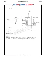
H. Wiring Diagram
Fig. 17
The maintenance of the electrical parts, and wiring must be made by a qualified electrician.
Wiring Colour Code.
Yellow/Green wire --- Grounding
Blue wire --- Neutral
Brown --- Live
Cautions:
If the motor does not work while the power voltage is on, first check the cut-out units.
E.G. check if the micro switch has been closed properly inside the change gear box.
Page 18
Instructions Manual for AL-320G (L141)
07/02/2018
Summary of Contents for AL-320G
Page 10: ...10 Thread Chart Page 10 Instructions Manual for AL 320G L141 07 02 2018 ...
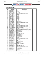
Page 20: ...20 AL 320 BED PARTS Page 20 Instructions Manual for AL 320G L141 07 02 2018 ...
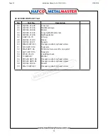
Page 23: ...23 AL 320 HEADSTOCK PARTS Page 23 Instructions Manual for AL 320G L141 07 02 2018 ...
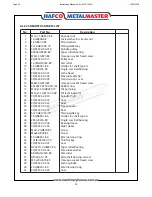
Page 27: ...27 AL 320 BACK GEARS PARTS Page 27 Instructions Manual for AL 320G L141 07 02 2018 ...
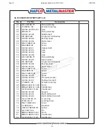
Page 30: ...30 AL 320 GEARBOX PARTS Page 30 Instructions Manual for AL 320G L141 07 02 2018 ...
Page 33: ...33 AL 320 APRON PARTS Page 33 Instructions Manual for AL 320G L141 07 02 2018 ...
Page 36: ...36 AL 320 COMPOUND SLIDE PARTS Page 36 Instructions Manual for AL 320G L141 07 02 2018 ...
Page 38: ...38 AL 320 TAILSTOCK PARTS Page 38 Instructions Manual for AL 320G L141 07 02 2018 ...


