background image

23

OPERATION MANUAL

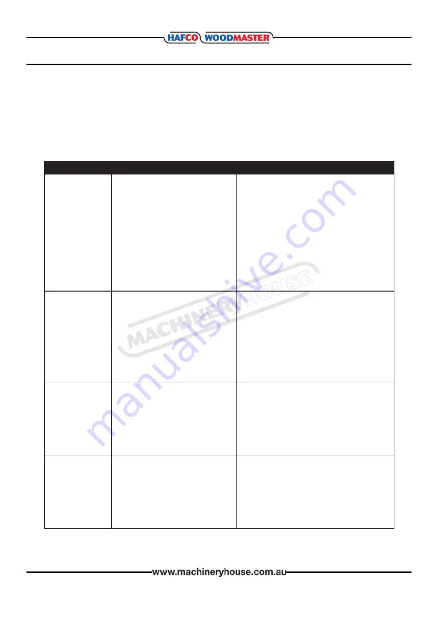
5.3 TROUBLESHOOTING

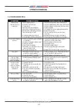
SYMPTOM

SYMPTOM

POSSIBLE CAUSE

POSSIBLE SOLUTION

Machine does not

start or a breaker

trips.

1. Stop push-button engaged/faulty.

2. Power switched OFF or at fault.

3. Thermal overload relay has tripped.

4. Wall circuit breaker tripped.

5. Plug/receptacle at fault/wired                  

     incorrectly.

6. Motor connection wired incorrectly.

7. Contactor not energized.

8. Wiring open/has high resistance.

9. ON/OFF switch at fault.

10. Start capacitor at fault.

11. Centrifugal switch at fault

12. Motor at fault.

1. Check magnetic switch/replace it.

2. Ensure power supply is switched ON

3. Reset trip load dial if necessary; replace.

4. Ensure circuit size is correct/replace.

5. Test for good contacts; correct the wiring.

6. Correct motor wiring connections 

7. Test all legs for power/replace if faulty.

8. Check and fix broken, disconnected wires

9. Replace switch.

10. Test/replace if faulty.

11. Adjust/replace centrifugal switch.

12. Test/repair/replace.

Machine stalls or is

underpowered

1. Feed rate too fast.

2. Workpiece material not suitable.

3. Dust collection ducting problem.

4. Motor overheated.

5. V-belt(s) slipping.

6. Run capacitor at fault.

7. Pulley/sprocket slipping on shaft.

8. Motor bearings at fault.

9. Motor at fault.

1. Decrease feed rate.

2. Ensure timber moisture is below 20%.

3. Clear blockages, use smooth wall duct,

4. Clean motor, let cool, and reduce load.

5. Tension/replace belt(s) ensure pulleys

    are aligned 

6. Test/repair/replace.

7. Replace loose pulley/shaft.

8. Test/repair/replace.

9. Test/repair/replace.

Excessive step 

(snipe)

(gouge at the end 

of the workpiece 

that is uneven with 

the rest of the cut).

1.  One or both of the bed rollers are

     set too high.

2. Rear table extension slopes down or 

    is not level with the table

3. Chip breaker or pressure bar set too

    low         

4. Workpiece is not fully supported as it

    leaves the thicknesser.

1. Lower the bed rollers 

2. Adjust the rear extension wing set screws 

     to make the extension level with the table 

3. Raise the height of the chip breaker or 

    pressure bar

4. Use a roller stands to properly support the

    workpiece as it leaves the thicknesser.

Workpiece stops/

slows in the middle

of the cut.

1. Depth of cut too deep.

2. Pitch/glue build-up on thicknesser

    components.

3. One or both of the bed rollers are set

    too low or too high.

4. Chip breaker or pressure bar set too 

    low

5. Feed rollers set too low or too high.

1. Reduce the depth of cut.

2. Clean planer components with a pitch/

    resin dissolving solvent.

3. Lower/raise the bed rollers

4. Raise the height of the chip breaker or

    pressure bar

5. Adjust the feed rollers to the correct height

Should any problems arise review the troubleshooting procedures in this section to find the 

possible problem or fix and adjust your machine.

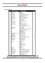
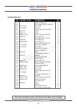
The spare parts view and the proceedure for ordering is layed out in the spare parts section.

Summary of Contents for T-13B

Page 1: ...OPERATION MANUAL Edition No T 13B 1 Date of Issue 11 2020 Model T 13B THICKNESSER Order Code W812 ...

Page 2: ...R MACHINE T 13B MODEL NO SERIAL NO DATE OF MANF NOTE This manual is only for your reference Owing to the continuous improvement of the HAFCO machines changes may be made at any time without obligation or notice Please ensure the local voltage is the same as listed on the specification plate before operating this electric machine Distributed by www machineryhouse co nz MACHINE DETAILS ...

Page 3: ... 2 Setting Up the thicknesser 13 Mounting Option 13 Attaching the Handwheel 13 Attaching the Dust Hood 13 3 3 Electrical Installation 14 3 4 Full Load Current Rating 14 3 5 Test Run 15 4 OPERATION 4 1 Basic Controls 15 4 2 Workpiece Inspection 16 4 3 Basic Operation 17 5 MAINTAINANCE 5 1 Lubrication 19 Feed Chain Lubrication 19 Main Bearings 20 5 2 ADJUSTMENTS 20 Motor Brush Replacement 20 Table L...

Page 4: ... Cutters No 2 Cutter Block Diameter mm 50 Cutter Block Speed R P M 8500 Feed Rate m mm 6 Length of Table mm 190 Length of Table with Extensions mm 630 Feed Speed M Min 6 Dust Outlet Diameter mm 102 65 Motor Power Watts 1500 Power Requirement 240V 50Hz 1Ph Full Load Current Rating Amps 7 Minimum Circuit Size Amps 10 Floor Space W x D x H 600 x 630 x 480 Shipping Dimensions L x W x H 630 x 410 x 480...

Page 5: ... FRAME F CUTTERHEAD MOTOR ASSEMBLY B RETURN ROLLERS G HEIGHT GAUGE C DUST CHUTE H OUT FEED EXTENSION WING D HAND WHEEL I IN FEED EXTENSION WING E LIFTING HANDLES J ON OFF SWITCH A B D D E G J H 1 2 IDENTIFICATION FIG 1 F H C I ...

Page 6: ...r distributor and report it imeadiately If the machine has been damaged while in transit save all the packing materials for possible inspection by the carrier Do not dispose of the packing materials until the machine has been assembled and any shipment disputes have been settled A Dust Port Adaptor E Magnets B Crank Handle F Crank Handle Screw Washer C Manual G Hex Key D Socket Head Screw H Machin...

Page 7: ...o the dust created by power sanding sawing grinding drilling and other construction activities may cause serious and permanent respiratory or other injury including silicosis a serious lung disease cancer and death Avoid breathing the dust and avoid prolonged contact with dust Some examples of these chemicals are q Lead from lead based paints q Crystalline silica from bricks cement and other mason...

Page 8: ...and machine controls can be seen clearly Position or shade lighting sources so that they do not shine in the operator s eyes or cause any glare and reflections Ensure that the floor space around the equipment is sufficient to enable you to machine the size of work piece being processed safely without bumping into other workers or equipment Woodworking machines should be fitted with efficient and w...

Page 9: ...ders back or neck resulting from repetitive motion awkward posture extended lifting and pressure grip Other Hazards Slips and falls from and around machinery during maintenance Unstable equipment that is not secured against falling over Safe access to from machines access egress Fire or explosion Pressure injection injuries from the release of fluids and gases under high pressure Electrical Hazard...

Page 10: ...top 5 Do not exceed maximum 0 8mm depth of cut for timber wider than 152mm 6 Ensure all locks are securely tightened before operating the machine 7 Start the dust extraction unit before using the machine 8 Faulty equipment must not be used Immediately report suspect machinery OPERATIONAL SAFETY CHECKS 1 Never leave the machine running unattended 2 Timber less than 300 mm in length must not be plan...

Page 11: ... tables during operation DISCONNECT BEFORE ADJUSTMENTS To avoid unexpected start up and serious personal injury always disconnect the thicknesser from the power before performing adjustments maintenance or service PINCH POINTS Beware of pinch points that can cause serious damage to fingers and hands especially if using a support roller stand on the out feed Fig 2 1 It is best practice to wait for ...

Page 12: ...onal stand Order Code W810 The machine has inbuilt lifting handles Fig 2 2 to assist in the lifting process Make sure that machine is kept in a level position while lifting 3 INSTALLATION 3 1 SELECTING A LOCATION Check the weight and footprint specifications of your machine to ensure that the bench or stand is able to support both the machine and the work piece Placement Location Consider the exis...

Page 13: ...screw Tighten screw using supplied hex wrench Fig 3 3 ATTACHING THE HAND WHEEL Fig 3 4 The Dust Port is used to direct the waste away from the machine and is most commonly used when the thicknesser is connected to a dust collector It has a 4 port to accommodate most dust collection systems To install 1 Install the dust port to the rear of the thicknesser and attach using the 2 socket head cap scre...

Page 14: ...load rating and if the machine is overloaded for a long period of time damage overheating or fire may be caused to the motor and circuitry This is especially true if connected to an undersized circuit or a long extension lead To reduce the risk of these hazards avoid overloading the machine during operation and make sure it is connected to a power supply circuit that meets the requirements 3 4 FUL...

Page 15: ...on switch which will trip if the motor becomes too hot To reset the switch move the ON OFF switch to OFF wait a few minutes to allow the motor to cool then press the reset button Fig 4 1 ON OFF Button Reset Button Height Adjustment Handle The thicknesser depth of cut is controlled by using the elevation crank on top of the machine Rotating the crank clockwise raises the cutterhead Fig 4 2 Fig 4 2 ...

Page 16: ...ne is only intended for planing workpieces of natural wood fiber Attempting to plane workpieces of any other material could lead to serious personal injury and machine damage Foreign Objects Inspect lumber for defects and foreign objects nails staples imbedded gravel etc If you have any question about the quality of your lumber do not use it Remember wood stacked on a concrete floor can have small...

Page 17: ... OPERATION Operating Tips q Where ever possible use the full width of the thicknesser cutters If the width is smaller than the width of the cutters alternate the cutting path between the left the right and the middle of the table to evenly distribute the wear across the cutters q Scrape all glue off joined boards before putting the timber through the thicknesser q ONLY machine natural wood Do not ...

Page 18: ...4 6 CHIP MARKS OR INDENTATIONS Reason Chip indentation or chip bruising is the result of wood chips not being removed from around the cutterhead Instead they are deposited on the planed surface and crushed into the workpiece by the outfeed roller This condition can be caused by a number of reasons some of which are a The type of lumber being planed Certain species have a tendency to chip bruise b ...

Page 19: ...re to clean off with a non flammable tar and pitch remover 3 Any moving parts should be cleaned regularly with a penetrating oil and lubricated with a light coating of medium weight machine oil FEED CHAIN LUBRICATION To lubricate feed roller chain drive 1 DISCONNECT THE MACHINE FROM THE POWER 2 Remove the height adjustment crank handle A in Fig 5 1 2 Remove the 4 socket head cap screws that secure...

Page 20: ...e inspected every 10 15 hours of use To inspect 1 DISCONNECT MACHINE FROM THE POWER SUPPLY 2 Remove the Brush Holders one of which is shown at A The other is located in the same position on the rear of the motor assembly The Brush Holder can be removed using a flat blade screwdriver Fig 5 4 3 Once the brush has been removed inspect the carbon B the spring C and the wire D 4 If the carbon of either...

Page 21: ...djust as required 4 Tighten the screws and recheck the level Fig 5 7 D THICKNESS SCALE ADJUSTMENT The scale located on the right hand side of the thick nesser shows the thickness of the finished work piece Fig 5 8 To make sure the scale is set correctly run a piece of timber through the thicknesser and measure the finished size of the timber If the measurment on the scale is not the same as the ti...

Page 22: ...de of thicknesser and remove the blade guard Fig 5 9 5 Carefully turn the cutter head by hand until the six gib screws are facing the top of the machine 6 Loosen and remove six bolts from gib Fig 5 10 7 Remove the gib plate using the magnets provided Fig 5 11 NOTE Blade edges are extremely sharp Keep fingers away from the blades at all times 8 The blade is located in position by two pins Gently li...

Page 23: ...oth wall duct 4 Clean motor let cool and reduce load 5 Tension replace belt s ensure pulleys are aligned 6 Test repair replace 7 Replace loose pulley shaft 8 Test repair replace 9 Test repair replace Excessive step snipe gouge at the end of the workpiece that is uneven with the rest of the cut 1 One or both of the bed rollers are set too high 2 Rear table extension slopes down or is not level with...

Page 24: ...d rate 4 Reduce the depth of cut 5 Properly adjust the bed roller height 6 Adjust sides of chip breaker until correct Furry grain 1 Workpiece has high moisture content or surface wetness 2 Dull cutter blades or inserts 1 Allow workpiece to dry if moisture content is over 20 or has surface wetness 2 Rotate replace cutter blades or inserts Lines or ridges runing the length of the workpiece 1 Nicked ...

Page 25: ...otification HOW TO ORDER SPARE PARTS 1 Have your machines model number serial number date of manufacture on hand these can be found on the specification plate mounted on the machine 2 A scanned copy of your parts list diagram with required spare part s identified 3 Go to www machineryhouse com au contactus and fill out the enquiry form attaching a copy of scanned parts list Edition No T 13B 1 Date...

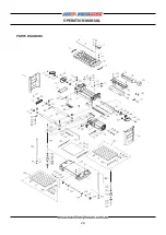
Page 26: ...26 OPERATION MANUAL PARTS DIAGRAM ...

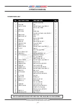
Page 27: ...lat washer 5MM 0 Roller cap Socket pan head screw M6X12 Top cover Grip Flat washer 6MM Left cover Retaining ring φ15 Chain 410 26 Sprocket Socket head screw M5X35 Spacer Gear box assembly Pinion Ball bearing 6203 3Z Elevating nut LH Set screw M5X6 Cable clamp UC 1 5 Socket head screw M5X10 Chain cover Pan head screw M5X8 Lock washer φ5 Serrated washer 5MM Socket head screw M5X10 Belt cover Elevati...

Page 28: ...crew M5X12 Cutterhead pulley Motor pulley Belt 135J6 Hex nut M16X 5 LH Screw Dust exhaust port Connecting port Socket head screw M5X10 Flat washer 5MM Dust chute Chute plate Flat head tap screw ST4 2X13 Hex wrench 4MM Magnet Spring 4MM Bearing block Left retainer II Flat washer φ5 Lock washer φ5 Socket head screw M5X12 Outfeed roller Right retainer I Infeed roller Power cord Motor Switch Circuit b...

Page 29: ...de Table Socket head screw M5X8 Flat washer φ5 Outfeed extension table Flat washer φ5 Lock washer 12 Socket head screw M5X8 Elevating screw RH Flat washer Ball bearing 6000ZZ Bearing clamp plate Base Infeed extension table Bushing Spring washer 8MM Table support Lock washer φ6 Socket head screw M6X20 Extension table Hex head bolt M6X20 Hex nut M6 Bevel gear Socket head screw M5X12 Shaft Flat washe...

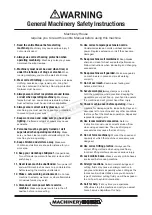
Page 30: ...n the off position before re connecting 14 Use correct amperage extension cords Undersized extension cords overheat and lose power Replace extension cords if they become damaged 15 Keep machine well maintained Keep blades sharp and clean for best and safest performance Follow instructions when lubricating and changing accessories 16 Keep machine well guarded Make sure guards on machine are in plac...

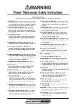
Page 31: ...ll the work piece into the cutter head Always keep hands clothing hair away from the infeed roller during operation to prevent serious injury 13 Never look inside thicknesser Wood chips fly around inside the thicknesser at a high rate of speed Do not look inside the thicknesser remove guards or covers during operation 14 Operating position The work piece may kick out during operation To avoid gett...

Page 32: ... Strategies Recommended for Purchase Buyer User Heavier timber must be supported Eliminate avoid loose clothing Long hair etc Isolate power to machine prior to any checks or maintenance Be sure that when rising and falling planner tables hands are well away from locating clamping and pivoting area Care must be taken when handling knives MEDIUM Make sure all guards are secured shut when machine is ...

Reviews: