32
repeat percentages or values. When all entries are made, return to the Controller MODE
options and select CURVE.
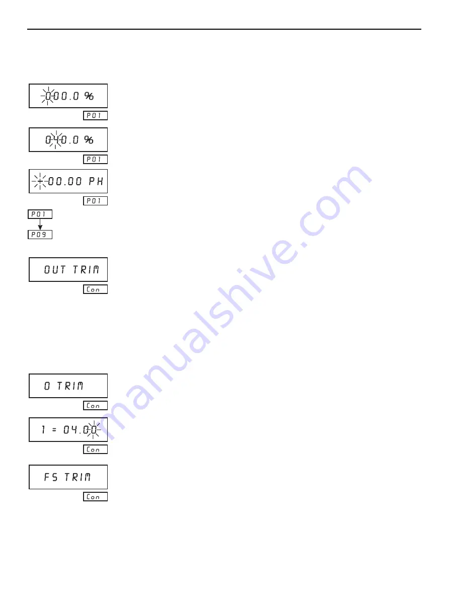
Example—(Assuming PH was selected for the controller MODE)
Press
ENTER
.
Select the percent (of reagent addition) for the first point (X axis) by pressing the
RIGHT
ARROW
key and the
DOWN ARROW
key or the
UP ARROW
key.
Press
ENTER
.
Select the PH value by pressing the
RIGHT ARROW
key and the
DOWN ARROW
key or the
UP ARROW
key.
The Controller prompts the user to continue entering the percentages and PH values
through nine entries (corresponding to number of points selected). The green LED display
continues to show which point selection is being made at any time even if the user scrolls
back to the beginning of the sequence.
Press
ENTER
then
CLEAR
followed by the
DOWN
ARROW
key to advance to:
The function of the output trim adjustment is slightly different from the rest of the edit
functions. When the zero (minimum scale) trim is selected, the controller output is driven
to zero (minimum scale), and the output value is displayed with the right hand digit
flashing. If the output is too low, pressing and holding the
UP
ARROW
key causes the
output to ramp up.
When the output is correct, release the
UP ARROW
key. If the output is too high, use the
DOWN ARROW
key. If a large adjustment is required (e.g., adjusting the controller zero
from 4 mA to 0 mA), use the
RIGHT ARROW
key to move the flashing digit to the left.
When the
UP
or
DOWN ARROW
keys are used, the output ramps faster.
Press
ENTER
.
Press
ENTER
.
This is the trim controller zero setting (in terms of mA output).
Press the
DOWN ARROW
key or the
UP ARROW
key to adjust the output.
Press
ENTER
.
Summary of Contents for EC1000
Page 2: ...2...
Page 8: ...8...
Page 12: ...12...
Page 14: ...14...
Page 16: ...16...
Page 18: ...18 Figure 1 Controller Front Panel...
Page 20: ...20 Figure 2 Pump Module...
Page 24: ...24 Figure 6 pH Control Loop...
Page 54: ...54...
Page 56: ...56...
Page 58: ...58 Figure 12 Controller Installation Panel Mount...
Page 61: ...61 Figure 15 Installing the pH ORP Electrode Figure 16 Flow Thru Cell...
Page 70: ...70...
Page 73: ...73 6 4 Calibration See Section 2 3 Calibration Figure 21 Priming Tee Operation...
Page 74: ...74...
Page 80: ...80...
Page 83: ...83 Figure 24 Sensor Replacement...
Page 85: ...85 Figure 25 Hach One pH Process Electrode...
Page 89: ...89 Figure 26 Pump Module Plumbing Diagram...
Page 102: ...102...
Page 103: ......
Page 104: ......
Page 105: ......
Page 106: ......
Page 108: ...108...
Page 112: ...112...
Page 116: ...116...
Page 122: ...122...
Page 123: ...123...
Page 124: ......


