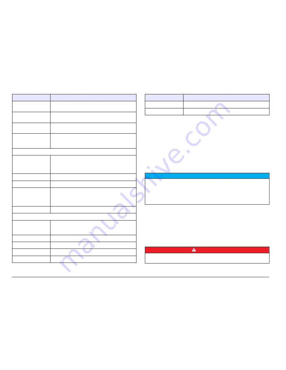
Hach Accu4 User Manual Download Page 4

Specification

Details

Sensor-to-controller
distance

9 m (30 ft) maximum

1

Power requirements

90–130 VAC (115 VAC nominal) or 180–260 VAC
(230 VAC nominal), 50/60 Hz, 10 VA maximum

Relays

Four electromechanical relays; SPDT (Form C)
contacts; 115/230 VAC, 5 A @ 30 VDC resistive

Analog outputs

Two isolated 0.00–20.00 mA or 4.00–20.00 mA outputs
each with 0.004 mA (12–bit) resolution; up to 600 ohm
load capacity

Mechanical:

Enclosure

NEMA 4X; polycarbonate face panel, epoxy-coated
cast aluminum door and case with four 13-mm (½–in.)
cable entry holes, nylon mounting bracket and stainless
hardware

Mounting

Panel, surface or pipe mount

Net weight

2.3 kg (5 lb)

Fuses

One type T, 80 mA, 250 V slow-blow fuse for the 230 V
line power circuits, 5 mm x 20 mm; one type T,
100 mA, 250 V slow-blow fuse for the 115 V line power
circuits, 5 mm x 20 mm

Certifications

15 year environmental friendly use period

Accu4 system performance:

Measurement range

0.000–100.0 NTU; auto-ranging and automatic decimal
point shift above 1.000 NTU and 10.00 NTU (same for
other measurement units)

Measurement units

NTU, TEF, FNU or FTU

Signal averaging

0 to 60 seconds

System accuracy

±2% of reading, all ranges

Sensitivity

0.001 NTU

Specification

Details

Repeatability

0.1% of span or better

Temperature drift

Zero and span: 0.01% of span per °C

1

Contact the manufacturer if a longer distance is necessary.

General information

In no event will the manufacturer be liable for direct, indirect, special,
incidental or consequential damages resulting from any defect or
omission in this manual. The manufacturer reserves the right to make
changes in this manual and the products it describes at any time, without
notice or obligation. Revised editions are found on the manufacturer’s
website.

Safety information

N O T I C E


The manufacturer is not responsible for any damages due to misapplication or
misuse of this product including, without limitation, direct, incidental and
consequential damages, and disclaims such damages to the full extent permitted
under applicable law. The user is solely responsible to identify critical application
risks and install appropriate mechanisms to protect processes during a possible
equipment malfunction.

Please read this entire manual before unpacking, setting up or operating
this equipment. Pay attention to all danger and caution statements.
Failure to do so could result in serious injury to the operator or damage
to the equipment.
Make sure that the protection provided by this equipment is not impaired.
Do not use or install this equipment in any manner other than that
specified in this manual.

Use of hazard information

D A N G E R


Indicates a potentially or imminently hazardous situation which, if not avoided, will
result in death or serious injury.

4


English

Summary of Contents for Accu4

Page 1: ...DOC023 97 80356 Accu4 T53 8320 01 2013 Edition 1 User Manual...

Page 2: ...English 3 29 2...

Page 3: ...bubble trap on page 27 Mechanical Light sources Two near infrared 880 nm wavelength LEDs Specification Details Power requirements 5 V supplied by the controller to the light sources and detectors Proc...

Page 4: ...1 of span per C 1 Contact the manufacturer if a longer distance is necessary General information In no event will the manufacturer be liable for direct indirect special incidental or consequential dam...

Page 5: ...f a fuse or current limiting device This symbol indicates that the marked item requires a protective earth connection If the instrument is not supplied with a ground plug on a cord make the protective...

Page 6: ...e by any applicable regulation and to have sufficient and appropriate mechanisms in place for compliance with applicable regulations in the event of malfunction of the instrument The Accu4 low range t...

Page 7: ...0 mm 4x 4 Mounting bracket 9 Pan head screws M6 x 1 0 x 100 mm for pipe mount 4x 5 Ground screw green 10 Pan head screws M6 x 1 0 x 150 mm for panel mount 4x Installation W A R N I N G Multiple hazard...

Page 8: ...er source Protected from corrosive fluids Note If exposed to direct sunlight the operating temperature of the controller may increase above the specified limit Direct sunlight may also decrease the di...

Page 9: ...hold the cables securely when tightened Do not put more than one cable in a cable strain relief Close all unused cable entry holes with applicable plugs to keep out moisture Close all unused cable st...

Page 10: ...g strip General wiring procedure W A R N I N G Potential Electrocution Hazard Always disconnect power to the instrument when making electrical connections Connect wiring to the controller as shown in...

Page 11: ...e controller with conduit or a power cable Make sure that a circuit breaker with sufficient current capacity is installed in the power line The circuit breaker size is based on the wire gauge used for...

Page 12: ...oise may interfere with the sensor signal Table 1 AC power wiring information Input voltage Terminal Description Color North America Color EU 115 VAC single phase 3 Hot Black Brown 230 VAC single phas...

Page 13: ...put 1 and Outputs 2 that represent the measured turbidity Use the analog outputs for analog signaling or to control external devices Refer to Figure 5 on page 10 and General wiring procedure on page 1...

Page 14: ...B C and D that are opened or closed by the measured turbidity or diagnostics Refer to Configure the relays on page 19 The relay outputs are not powered Refer to General wiring procedure on page 10 Fi...

Page 15: ...TTL terminals When this connection is broken the applied hold or transfer releases Note The TTL input feature is disabled during calibration and system diagnostic tests that are started by the user Pl...

Page 16: ...tion ball valve in IPS 2 Isolation ball valve in IPS 5 Process input 3 To open drain 6 Inlet in NPT female Connect the sample stream Install the sample line into a larger process pipe to minimize inte...

Page 17: ...U Go to the Main Menu screen and cancel the procedure to change a setting ESC Go back one menu level or cancel the procedure to change a setting ENTER Confirm a menu selection or confirm changes to a...

Page 18: ...2 value mA Startup Select the language Select the display language default English 1 Push MENU and select CONFIGURE LANGUAGE 2 Use the UP and DOWN arrows to select the language 3 Push ENTER Start the...

Page 19: ...d stay at 20 mA SET TRANSFER Set the transfer value of the analog output 4 or 0 to 20 mA default 20 mA During calibration the analog outputs can be held transferred or kept active When transfer is sel...

Page 20: ...low HIGH default The relay is energized when the measured turbidity is higher than the setpoint LOW The relay is energized when the measured turbidity is lower than the setpoint SET SETPOINT Set the...

Page 21: ...alibration only W A R N I N G Chemical exposure hazard Obey laboratory safety procedures and wear all of the personal protective equipment appropriate to the chemicals that are handled Refer to the cu...

Page 22: ...Pour the sample of known value or prepared standard suspension 20 NTU or 40 NTU into the calibration funnel until the flow chamber is full 9 Put the calibration funnel in the funnel holder Enter the v...

Page 23: ...ory defaults Enable or disable the passcode Enable the passcode to prevent unauthorized changes to the configuration settings and calibrations The passcode is disabled by default The passcode is 3456...

Page 24: ...7 for the replacement fuse kit 3 Close the controller Turn the four screws to tighten Replace a light source or detector D A N G E R Electrocution hazard Remove all power from the instrument and relay...

Page 25: ...material Clean the flow chamber Refer to Clean the flow chamber on page 23 Table 5 Status messages continued Message Description Solution CHAMBER UNKNOWN The sensor cable wiring is not connected or n...

Page 26: ...y meter on the NO and NC relay output terminals to confirm the relay status selected SIM SENSOR Set the simulated turbidity measurement value 0 00 to 100 00 default 0 35 NTU Use this option to confirm...

Page 27: ...d Use of non approved parts may cause personal injury damage to the instrument or equipment malfunction The replacement parts in this section are approved by the manufacturer Note Product and Article...

Page 28: ...t source or detector 1 8220F1078 Accessories Description Quantity Item no Model 8320 turbidity sensor Bubble trap head regulator 1 4668000 Lubricant silicone 2 g 6M0920 Flask class A 2 L 1 2489454 For...

Page 29: ...7 psig 3 8 LPM 1 GPM 9 5 0 19 1 9 LPM 0 05 0 5 GPM 1 9 LPM 0 5 GPM 48 880 nm LED 5 V in NPT 3 8 in in NPT PVC PPO x x 285 x 172 x 400 mm 11 21 x 6 79 x 15 75 in 4 5 kg 10 lb 15 T53 LCD 128 x 64 LED 13...

Page 30: ...00 20 00 mA 4 00 20 00 mA 0 004 mA 12 600 NEMA 4X 13 mm in 2 3 kg 5 lb T 80 mA 250 V 230 V 5 mm x 20 mm T 100 mA 250 V 115 V 5 mm x 20 mm 15 Accu4 0 000 100 0 NTU 1 000 NTU 10 00 NTU NTU TEF FNU FTU...

Page 31: ...pment Regulation IECS 003 A A Cet appareil num rique de classe A r pond toutes les exigences de la r glementation canadienne sur les quipements provoquant des interf rences FCC 15 A FCC 15 1 2 FCC 15...

Page 32: ...1 8320 1 6 2 2 7 3 2 8 in NPT 4 9 5 in NPT 10 2 3 2 1 3 4 2 4 32...

Page 33: ...3 1 6 inID 8 2 7 M6 8 3 2 8 M6 x 1 0 x 20 mm 4 4 9 M6 x 1 0 x 100 mm 4 5 10 M6 x 1 0 x 150 mm 4 9 m 30 ft 29 1000G3088 001 4 33...

Page 34: ...4 NEMA IP NEMA 4X IP66 3H1091 3H1230 4 3 11 4 mm 0 17 0 45 in ESD ESD 5 34...

Page 35: ...5 1 2 5 2 RS232 6 2 3 TTL 7 4 4 8 6 NEMA IP 6 35...

Page 36: ...3 m 10 ft 18 12 AWG 3 m 10 ft 60 C 140 F 18 AWG 1 5 35 35 3 4 1 115 VAC 3 230 VAC 4 115 230 VAC 2 N PE 35 7 2 36...

Page 37: ...7 2 TB 1 12 18 13 19 14 20 15 21 16 22 0 00 20 00 mA 4 00 20 00 mA 1 2 5 35 35 42 600 37...

Page 38: ...A B C D 43 35 8 3 18 12 AWG 18 AWG 5 A 30 V RMS 42 2 V PEAK 60 VDC 30 V RMS 42 2 V PEAK 60 VDC 8 1 A 5 2 C 6 3 0 1 F 600 V 7 100 230 VAC 4 100 1 W 8 2 N 3 NC COM TTL 38...

Page 39: ...TTL 5 35 TTL HOLD XFER ACTIVE HOLD XFER 42 43 ACTIVE TTL TTL TTL TTL 9 10 9 1 in NPT 6 2 7 in IPS 3 in IPS 8 in NPT 4 9 in IPS 5 in IPS 39...

Page 40: ...10 1 in NPT 4 in IPS 2 in IPS 5 3 6 in NPT 11 11 1 2 12 T53 4 40...

Page 41: ...12 1 2 4 MENU Esc ENTER RIGHT LEFT UP DOWN 13 MENU ESC 30 RIGHT LEFT ENTER UP DOWN 13 1 1 3 1 mA 3 2 2 1 A C RELAY A C 2 3 DOWN 2 mA 1 MENU CONFIGURE LANGUAGE 2 UP DOWN 3 ENTER 41...

Page 42: ...N OFF ACCU4 8 UP DOWN RIGHT 3 ENTER 1 MENU CONFIGURE SET OUTPUT 1 2 2 SET 4mA or 0mA VALUE 4mA 0mA 4 mA 0 mA 0 00 100 00 SET 20mA VALUE 20 mA 20 mA 0 00 100 00 0 4 mA 20 mA 20 mA SET TRANSFER 4 0 20 m...

Page 43: ...ATION LOW ALARM 0 00 100 00 HIGH ALARM 0 00 100 00 LOW DEADBAND 0 00 10 00 HIGH DEADBAND 0 00 10 00 OFF DELAY 0 300 ON DELAY 0 300 PHASE SET SETPOINT 0 00 100 00 DEADBAND 0 00 10 00 OVERFEED TIMER 0 0...

Page 44: ...4000 NTU Formazin MSDS SDS 4 NH2 2H2SO4 5 CH2 6N4 50 1 0 2 2 1000 mL 3 1 5 00 500 mL 4 2 50 00 500 mL 5 50 0 mL 1 50 0 mL 2 4000 NTU 6 25 C 3 C 77 F 5 4 F 24 7 1 8 20 NTU 40 NTU a 20 NTU 10 mL 4000 N...

Page 45: ...AL ENTER PRIMARY or SAMPLE CAL CONFIRM CAL OK CONFIRM FAILURE ENTER CAL EXIT CAL REPEAT 4 ENTER Confirm Active ESC 1 2 3 42 4 ENTER CONFIRM ACTIVE Confirm Active 5 ENTER 2 mA 0 20 mA 4 mA 20 mA 0 mA 1...

Page 46: ...3456 1 MENU CONFIGURE SET PASSCODE 2 UP DOWN TEST MAINT CALIBRATE TEST MAINT 3 ENTER 1 a 3 CALIBRATE b c 2 1 8 3 4 5 6 7 O 8 1 8 1 35 2 5 35 49 3 O 44 46...

Page 47: ...TER 5 5 ANALYZER OK ANALYZER FAIL Source 1 or 2 OK 1 2 SOURCE 1 or 2 FAIL 1 2 46 DETECT 1 or 2 OK 1 2 DETECT 1 or 2 FAIL 1 2 46 5 CHAMBER OK CHAMBER DIRTY 46 CHAMBER UNKNOWN 46 RLY A B C D ACTIVE A B...

Page 48: ...VERFEED RESET RLY A B C D COUNTING A B C D 1 MENU TEST MAINT 2 CHECK CAL HOLD 30 OUTPUT 1 or 2 1 2 0 4 20 mA 4 05 mA RELAY A B C D A B C D SIM SENSOR SIM 0 00 100 00 0 35 NTU 3 ENTER ESC 1 29 2 3 4 5...

Page 49: ...x 1 0 x 100 mm 4 8H1217 400 M6 x 1 0 x 150 mm 4 8H1217 600 1 1000A4F3249 101 8320 1 8220G1060 O 1 8220G1330 204 1 8220C2F1076 1 8320A1074 001 O 1 8220G1320 204 O 1 5H1288 O 1 5H1251 1 8220F1078 8320...

Page 50: ......

Page 51: ......

Page 52: ...ach com www hach com HACH LANGE GMBH Willst tterstra e 11 D 40549 D sseldorf Germany Tel 49 0 2 11 52 88 320 Fax 49 0 2 11 52 88 210 info hach lange de www hach lange de HACH LANGE S rl 6 route de Com...

Reviews: