ES0755 rev A 1/11
30
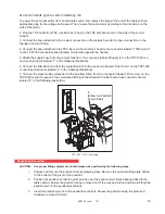
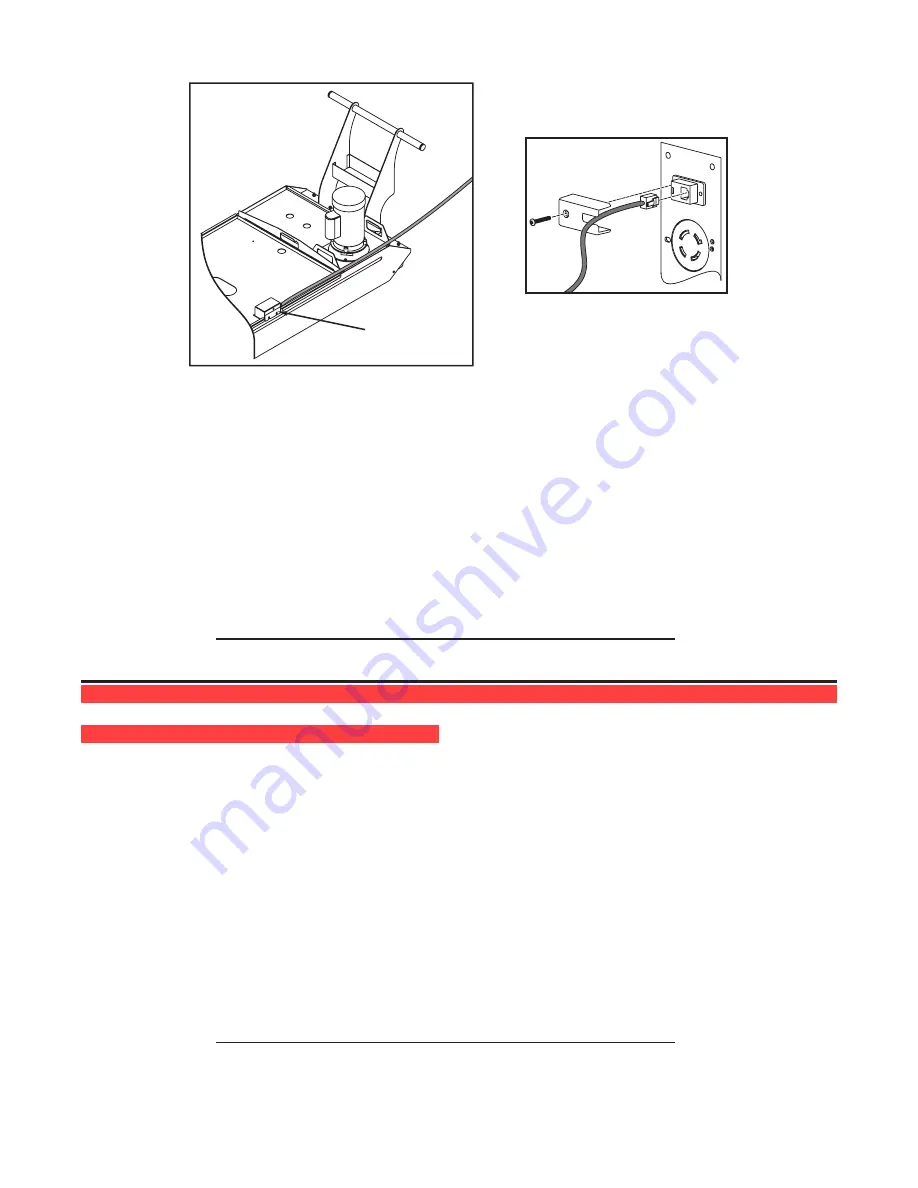
Coolant Level
Sensor
55 Gallon tank shown
4. Connect the cable to the Coolant Level Gauge plug located on the bulkhead at the back of the X-axis table.
Remove the cover from the RJ-12 style connector, plug in coolant level sensor cable, and replace cover.
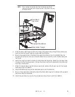
5. Select the Current Commands screen on the operator’s pendant and manually move the float up and down
to ensure that the display reflects a corresponding change in the coolant level.
6. Connect the Standard coolant line (3/4” O.D.) to the Standard pump.
7.
If machine includes Through the Spindle Coolant option, attach the 1/2” O.D. coolant line to the TSC pump.
8. Fill coolant tank with coolant.
Warning
Mineral cutting oils will damage rubber based components throughout machine.
NOTE:
Before operating the coolant system, ensure the drain is positioned
half way over tank strainer.
c
hiP
e
vacuation
c
hiP
a
uGer
I
nstallation
1.
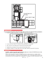
Unpack the discharge tube.
2.
Install the discharge tube into place. Attach with eight SHCS and locking washers and tighten
uniformly.
3.
After machine start-up, check the operation of the auger to ensure the direction of rotation will
move the chips toward the discharge tube. If the auger is turning so that the chips are not being
moved toward the discharge tube, change the bit switch in PARAM 209 from 1 to 0 or 0 to 1 to
establish a new forward direction.
MAINTENANCE
During normal operation, most chips are discharged from the machine at the discharge tube. However, very
small chips may flow through the drain and collect in the coolant tank strainer. To prevent drain blockage,
clean this trap regularly. Should the drain become clogged and cause coolant to collect in the machine’s pan,
stop the machine, loosen the chips blocking the drain, and allow the coolant to drain. Empty the coolant tank
strainer, then resume operation.
NOTE:
Augers and discharge tube are subject to wear. Abrasive swarf,
hard steel chips and continuous use will accelerate this wear.


