ES0755 rev A 1/11
10
6. Place the flat washer on the rod and thread both nuts onto the end of the rod. Before jamming the
nuts together, be certain they are both high enough to allow the insertion of the cotter pin into the
hole on the end of the cylinder rod. When the nuts are in place, jam the nuts together. Insert the
cotter pin into the hole on the end of the rod. Repeat for the remaining hydraulic cylinder.
7. Orient the cylinder so the hose will be away from the spindle head during operation and tighten
the shoulder screws.
8. Insert and tighten the hydraulic hose fitting (use teflon tape on the fitting) in the port of the coun
-
terbalance cylinder.
9. Remove the cap plug on the end of the hydraulic hose and connect it to the fitting that is now in
the port of the cylinder.
10. Charge the counterbalance system using dry nitrogen to about 1300 psi (measure at the bot-
tom of travel of the axis). Use all appropriate safety precautions and a supply bottle of adequate
volume. Each bottle that is to be charged is a 90 cubic foot bottle.
11. Power up the machine.
12. Zero return the column axis (Y-axis for HS machines, Z-axis for VS machines) only. The final
pressure of the system at the top of travel should be slightly more than 1250 psi. After the axis
has established zero, E-stop and note whether the axis has a tendency to slowly fall. This should
be monitored in the position page of the display as well as a visual determination. If the axis
falls at all, the counterbalance pressure should be slightly increased until the head cannot move
downward from the top of travel in a servo off condition. Take care not to overcharge the system,
an overcharge could cause the spindle head to move upward when in an E-stop condition at the
bottom of travel.
u
nblockinG
the
m
achine
CAUTION:
Before unblocking machine ensure that counterbalance cylinder
charging hose is attached to nitrogen tank and nitrogen tank is fully
charged to 1250psi.
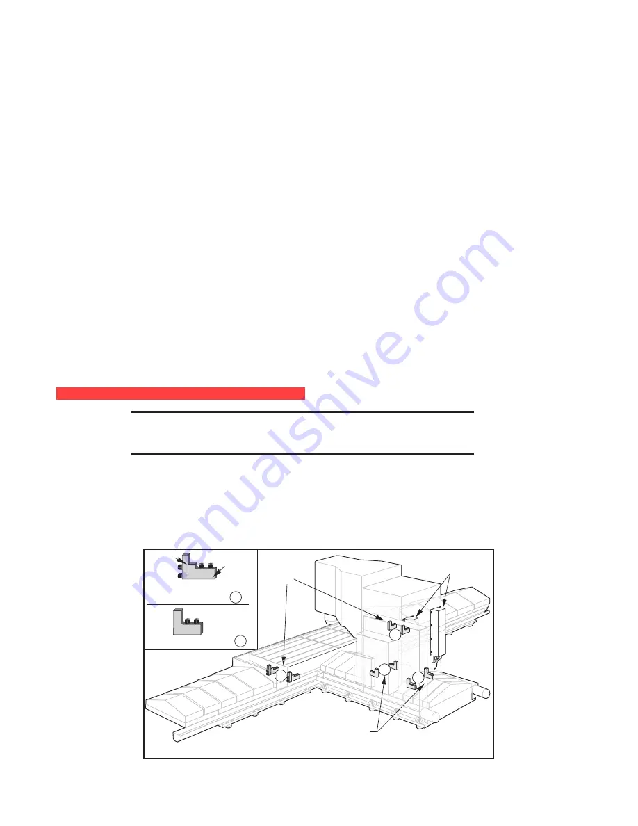
The counterbalance cylinders have been removed (for overhead clearance during shipping), and they must
be reinstalled and recharged with dry nitrogen prior to enabling the column axis (Y-Axis for HS machines, Z-
axis for VS machines). The table is secured for shipping by means of blocks that are bolted to the table base.
The column is secured for shipping by means of blocks that are bolted to the column base. The spindle head
is secured for shipping and a cover has been placed over the column axis ballscrew and that cover
must be
removed.
Shipping
Blocks for
Table
Shipping Blocks A
(2) Two-Piece
Shipping Blocks for Column
Counter Balance
Tanks
Shipping
(Stop)
Block
Support
Block
Portion
Clamp
Block
Portion
(6) Shipping Blocks B
A
B
B
B


