background image

ES0755  rev A      1/11

21

range of 700 to 750 psi. This is the “blocked system” pressure.
If necessary this pressure can be adjusted by turning the pressure adjusting screw (the vertically oriented 

screw with locknut), on the pump in a clockwise direction to increase pressure and counterclockwise to 

decrease pressure.
The tool changer is now fully connected and ready for alignment.

NOTE

:  Final alignment of the toolchanger to the machine spindle must be 

performed before the toolchanger can be used to change tools.

Tool Changer Installation

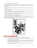
1. Before installing the eight leveling blocks on the bottom of the toolchanger base plate, thread in the metric 

SHCS into the holes located on each side of the leveling screws. 
2. Temporarily block tool changer up on its base plate and install the eight levelling blocks on the bottom of 

the base plate. Secure them with metric SHCS installed above. The leveling blocks with center holes are for 

the Main Leveling Screws in each corner; the solid leveling blocks are for the Intermediate Leveling Screws.

3. Verify that the four main leveling screws (the large hollow screws located at all four corners) and the four 

intermediate leveling screws (the hex head bolts located on each of the four sides of the base plate) are ad-

justed so that they are flush with the bottom of the tool changer’s base plate.

Center Holes In

HS3 Base With

Vertical Slots Of

Bracket

(3) M16x60mm

HS3

Toolchanger

HS3

Intermediate
Leveling Screws

Main Leveling Screws

Leveling Blocks

Metric

SHCS

Bracket Slots

Toolchanger

Bracket

Tool Changer and Base Plate

4. Lift tool changer with arm mechanism facing toward front of machine. Move the tool changer over the top of 

the pre-installed anchor bolts and lower it such that the hollow leveling screws slide over the anchor bolts.
5. An alignment bracket is used to provide initial “rough” alignment of the tool changer to the horizontal mill. 

Attach the alignment bracket to the base of the tool changer using three M16 X 60mm metric socket head cap 

screws (Haas P/N 40-0039). 

Install, but do not tighten screws at this time.

 In addition, it may be necessary 

to move the tool changer’s base plate a small amount to bring the alignment bracket into its proper position.
6. Place a bubble level on the tool changer’s base and using the four main leveling screws (the large 60mm 

hex screws located in the corners of the base plate) bring the tool changer base plate into level. During 

this leveling procedure, verify that the height of the slots on the vertical face of the alignment bracket are 

at the same elevation as the threaded holes in the pad located on the side of the milling machine’s base. If 

necessary, readjust the leveling screws to bring the alignment bracket to the proper elevation. 
7. When the tool changer is level and the four slotted holes in the alignment bracket are lined up with the 

threaded holes in the pad, attach the alignment bracket to the base of the mill using four 3/8-16 x 1¼ socket 

head cap screws. Finish attaching the bracket by tightening the three M16 cap screws.

Summary of Contents for HS-3

Page 1: ...round at the service entrance and should be routed in the same conduit as the input power to the machine A local cold water pipe or ground rod adjacent to the ma chine cannot be used for this purpose Input power to the machine must be grounded For wye power the neutral must be grounded For delta power a central leg ground or one leg ground should be used The machine will not function properly on u...

Page 2: ...servoir tank below the control box on the back of the machine is for the optional rotary table DO NOT use this as a connection for an auxiliary air line Auxiliary connections should be made on the left side of the air filter regulator WARNING When the machine is operating and the pressure gauge on the machine regulator drops by more than 10 psi during tool changes or pallet changes insufficient ai...

Page 3: ...n base mating flange Remove the table base assembly from the truck and set 12 away from the column Remove the X axis auger trough Move the column base to mate with the table base Be certain that all connecting bolts are in place but not tightened Attach the Pendant and Pendant Arm Support Assembly to the front of the table base Run the Pendant electrical wires under the table and connect them in t...

Page 4: ...n screws are actually engaged in the threads and that when the column base is in place and the mating surfaces are in contact that each screw is free to rotate Rough level by measuring from the floor to the bottom of the base very close to 2 inches Each of the leveling screws and pads should be in place at this time and it is advisable to take the measurement at each leveling screw location for be...

Page 5: ...m the machine or service parts of the air system on the machine 1 When the machine leaves the factory the air filter is empty and air lubricator and the lubricator reservoir tank are full However they should be checked and serviced if required before com pressed air is supplied to the machine 2 Connect the air blow gun to the air supply fitting on the machine See figure below 3 With the pressure o...

Page 6: ...cept during installation and service At those times only qualified electricians should have access to the panel When the main circuit breaker is on there is high voltage throughout the electri cal panel including the circuit boards and logic circuits and some components operate at high temperatures Therefore extreme caution is required Main Circuit Breaker Ground Line L1 L2 L3 1 Hook up the three ...

Page 7: ...Volt 74 75 76 74 75 76 HIGH VOLT 488 458V 457 429V 428 403V 402 377V 376 354V LOW VOLT 260 244V 243 227V 226 211V 210 195V 4 Transformer T5 supplies 24VAC used to power the main contactor There are two versions of this transformer for use on 240 and 400V machines 32 0964B and 32 0965B respectively The 240V transformer has two input connectors located about two inches from the transformer which all...

Page 8: ...tage is still outside these limits call the factory Next check the DC voltage displayed in the second page of the Diagnostic data on the display It is labeled DC BUS Verify that the displayed voltage matches the voltage measured at pins 2 and 3 of the Vector Drive 7 VDC 8 Electrical power must be phased properly to avoid damage to your equipment The Power Sup ply Assembly PC board incorporates a P...

Page 9: ... 468 445 456 5 456 433 444 6 444 420 432 7 432 This should produce a voltage on the secondary side of 234 243 V RMS L L Verify this and readjust the taps as required At the machine connect the cables at the input of the internal 230V transformer to the 227 243V taps Apply power to the machine and verify that the DC voltage between pins 2 and 3 of the Vector Drive 2nd and 3rd pins from the left is ...

Page 10: ... psi After the axis has established zero E stop and note whether the axis has a tendency to slowly fall This should be monitored in the position page of the display as well as a visual determination If the axis falls at all the counterbalance pressure should be slightly increased until the head cannot move downward from the top of travel in a servo off condition Take care not to overcharge the sys...

Page 11: ...cks 1 Disconnect both X axis way covers from the table and fully retract the way covers 2 Remove the blocks from the table base to prevent any inadvertent damage WARNING Be certain the machine is powered off when connecting or disconnecting servo motor cables 3 Uncoil the X axis servo motor cable and connect to the motor Do not attempt to dress the cable to the final configuration at this time but...

Page 12: ...Check cable clearances under the table for the full X axis travel and secure where necessary Unblocking the Column The column is held in place for shipping by means of blocks that are screwed into the column base There are two blocks in the front and two blocks in the rear of the column These blocks must be removed before normal operation of the column axis is possible To access the shipping block...

Page 13: ...e very rough leveling has taken place ensuring that the bottom of the two bases are very close to 2 inches off the floor The mating flanges of the two bases have been pulled into contact The screws that connect the two bases have been backed off and can rotate freely Overview of Leveling the Machine When leveling the machine the best results are achieved when the entire machine is leveled with res...

Page 14: ...nd the level ing process associated with the column base could alter the table base level If the screws do begin to bind the column base should be raised or lowered accordingly to free the screws While maintaining full face contact of the mating flange surface 2 Zero return all axes 3 Move the X axis to the center of travel 4 Place two levels at right angles to each other as close as possible to t...

Page 15: ...ree to rotate A binding of the screws will mean that the column base will have to be raised or lowered as necessary and the leveling process of the column base will need to be repeated 7 When the column base is level to earth in both directions the six center leveling screws should be lowered to touch the leveling pads 8 Remove the granite parallels from the column base Checking the Level of the C...

Page 16: ...ce of the table The line of motion of the Z axis will be checked by comparing it to the line of intersection of the two most convenient relative planes that of the X Z plane and the Y Z plane By assuring that each of these planes are perpendicular to the X Y plane within specification the machine geometry will be preserved Final Connection of the Column Base to the Table Base 1 Before inserting an...

Page 17: ...eadings are zero the column is flat to earth in the direction of the Y Power up the control axis Place the level on the spindle head parallel to the X axis Run the column through the range of travel If no deviation in the reading exists the column base exhibits no twist Place the granite parallels across the linear guide surfaces in front and behind the column Place the levels on the granite If th...

Page 18: ...e Y axis has not been affected by the leveling procedure of the X axis If it has use the steps described previously to make the necessary correction and then verify that the X axis is still correct Do not try to hurry this process This is a careful repetitive process that relies on modest adjustments for each step along the way If too large an adjustment is attempted the geometry will fail and it ...

Page 19: ...sure 700 PSI Pressure Hose 52 0008 1 2 JICF x 84 L Maximum Flowrate 1800RPM 10 5 GPM Return Hose 52 0000 1 2 JICF x 90 L Reservoir Volume 20 Gallons 1 Check level of hydraulic fluid in reservoir by inspecting the sight gage located on the side of the reservoir If necessary add hydraulic fluid DTE 25 to the reservoir until the level reaches the top of the sight gage 2 Connect pressure and return ho...

Page 20: ...ould be in a no load state This is accomplished by connecting the pump s discharge pressure hose directly to the inlet of the return filter connection Start and stop the motor 5 to 6 times to bleed any air from inside the pump Verify that the pump is discharging oil by feeling the discharge hose or cracking one of the fittings Operate the pump for at least 10 minutes without any load to remove any...

Page 21: ...S3 Intermediate Leveling Screws Main Leveling Screws Leveling Blocks Metric SHCS Bracket Slots Toolchanger Bracket Tool Changer and Base Plate 4 Lift tool changer with arm mechanism facing toward front of machine Move the tool changer over the top of the pre installed anchor bolts and lower it such that the hollow leveling screws slide over the anchor bolts 5 An alignment bracket is used to provid...

Page 22: ...ger Leveling Screws Leveling Screw Locations The four hex screw that go through the hollow leveling screws are used to anchor the tool changer to the floor after it has been leveled Insure that the tool changer angle bracket is attached 2 Loosen the eight sub plate bolts Do Not press POWERUP RESTART 3 To align tool changer a few preliminary steps must be done to avoid damaging the mill or the tool...

Page 23: ...m is fully rotated toward the magazine using the PAGE DOWN button b The arm is fully pulled in using the up arrow button c The arm is rotated fully clockwise or fully counterclockwise using the END button or the PAGE UP button until the arm is in a horizontal position d The arm is moved fully to the right using the right arrow button When the tool changer arm has been moved into its HOME position ...

Page 24: ...r number 211 omit the decimal point 14 Rotate the arm and switch the alignment jig to the other side Adjust as necessary so that the alignment pin inserts fully Repeat steps 11 13 until the dowel pin inserts fully in both sides of the arm 15 Tighten all locking nuts Home tool changer and magazine Exit from tool changer restore mode by pressing jog handle mode Setting the Tool Change Position Param...

Page 25: ...manual control of the tool changer 13 Using the tool change manual recovery cursor buttons move the tool changer carriage out of the machine enclosure to its home position and remove the alignment tool from the spindle and the tool changer arm 14 Complete the Tool Change Restore operation to close the tool changer door 15 POWER OFF and then POWER ON the machine Press the RESET button twice to clea...

Page 26: ...se flow increase speed or turn the adjusting screw clockwise to decrease flow speed NOTE Make adjustments in turn increments as small adjustments can cause large changes in speed d After completing the adjustment tighten the adjustment screw locknut Tool Changer Alignment Verification TC alignment must be verified before loading any tools Any adjustment or change to the machine level will affect T...

Page 27: ...ndle Orient Offset If spindle and arm do not line up reset Parameter 257 as described in Service Manual and continue moving closer until there is a maximum of 1 8 3 2 mm gap between the split tool halves ensuring the halves do not touch each other 9 Check the X and Y alignment of the double arm to the spindle by inserting the alignment dowel through both halves of the split tool The dowel should s...

Page 28: ...rm The tool changer should be operated at 100 rapid speed otherwise tool changer motion may jerk or be sluggish Tool Changer Enclosure Installation 11 11 1 2 3 4 6 8 10 9 8 11 7 5 12 13 1 Top Cover 2 Angle Bracket 3 Rear Guard 4 Guard Door 5 Hinge 6 J bolt Access Cover 7 Switch Box 8 Corner Panel 9 Cage Panel 10 Left Guard 11 Cage Bracket x3 12 Lower Tie Plate 13 Upper Tie Plate 14 Front Guard 14 ...

Page 29: ...t is important that the coolant tank is in place before leveling the machine to ensure there is adequate clearance height between the bottom of the auger trough and the tank 2 The Coolant Level Float Assembly is shipped in a separate box It consists of a housing float and cable Install the Coolant Level Float Assembly by lowering the float through the tank lid Line up the slots in the housing with...

Page 30: ...uger Installation 1 Unpack the discharge tube 2 Install the discharge tube into place Attach with eight SHCS and locking washers and tighten uniformly 3 After machine start up check the operation of the auger to ensure the direction of rotation will move the chips toward the discharge tube If the auger is turning so that the chips are not being moved toward the discharge tube change the bit switch...

Page 31: ...ke hose connection is tight the connection must be tight for the pump to prime itself If the motor is not turning check that the power cords are connected and the circuit breaker inside the control box is on The TSC pump will not pump if it is rotating backwards The motor rotation should be clockwise when viewed from the fan end CAUTION Running The TSC pump dry for more than 60 seconds can cause s...

Page 32: ...eck that the filter lid is securely closed 9 Run primary coolant system for ten minutes to prime the bag filter housing before using the TSC system 1000 Psi Through the Spindle Coolant Installation Place the 1000psi TSC assembly next to the coolant tank behind the machine with the hose connections facing the back of the machine Use the following coolant schematic as an aid for hose routing TSC CC ...

Page 33: ...ilter drain line from the coolant tank lid to the connector labeled Filter Drain on the TSC1000 connector panel items labeled 2 in the following illustration 7 Connect the plastic tubing ships tied to the Auxiliary Filter from the connector labeled Prime Line on the TSC1000 connector panel to the small elbow fitting on the Standard Coolant Pump hose connector items labeled 3 in the following illus...

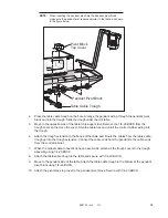
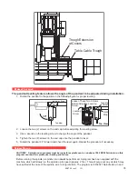
Page 34: ...he cover Snip the cable ties and unroll the control cabinet wiring into the trough 6 Attach the trough extension to the flange of the table bed Route the cables from the table cable trough up into the trough extension Connect the cable ends from the pendant to the cable ends from the control cabinet 7 When the proper cable connections have been made attach all the trough covers to the trough assem...

Page 35: ...rench on the leveling screw to change the angle of the pendant 4 Tighten the two 2 screws on the end cap once the pendant is level 5 Rotate the pendant 90 forward and check the level again Repeat the procedure if necessary Spindle Run in CAUTION Spindle run in program must be run before spindle can be run above 1000 RPM Failure to run this program can result in spindle over heating and failure Bef...

Page 36: ...t at 100 for 7 500 and 10 000 RPM ma chines Set at 150 for 15 000 RPM machines For machies equipped with a 50 taper spindle run spindle speed override at 50 The spindle should be checked periodically for spindle temperature rise If the temperature rises above 150 degrees start the program from the beginning If the temperature rises above 150 degrees a second time contact your dealer ...

Reviews: