Haas Door Commercial Instruction Manual
Rev. 7/15
© 2015 Haas Door Company
7
STEP 14
Raise the shaft assembly over the door. If 2 piece shaft with coupling is supplied, raise half the total shaft at a time. Rest the
end(s) of shaft on the horizontal track angle.
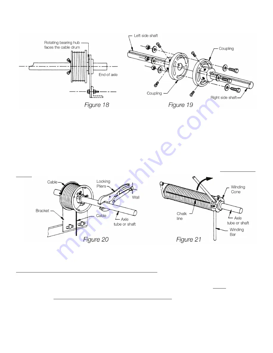
See Figure 19 For coupling installation.
STEP #17
Before going to Step 18. Be sure door is in locked position. If no lock is supplied, place a clamp in both tracks of door directly
above a roller to make sure door can not be raised at this tlme.
STEP # 18 WINDING SPRING
(see Figure 21)
Note: garage door springs can cause serious injury if not handled properly. Before winding the springs, make sure the lock is
engaged in the “locked” position. This will prevent the door from raising up by itself in the event the springs are over wound
or are too strong . Use two cold rolled steel rods approximately 18” long and the same diameter as the holes in the winding
cones (winding rods not furnished) 1/2” dia. for 1 3/4” & 2 5/8” springs and 5/8” dia. for larger springs. Do not use undersized
rods or other tools to wind springs. For your safety, position yourself on a sturdy ladder so that winding cone is either to your
right or to your left. Never stand directly in front of winding cones or winding bars. With one hand, insert one winding rod all
the way into the hole of the winding cone and wind the spring up one-quarter turn. With your other hand, insert the second
winding bar into the next hole, remove the upper winding bar and then take another one-quarter turn. Proceed in this man-
ner until you have made all the required number of turns. The number of turns are indicated on the spring tag attached to
the spring assembly. For example, if the tag says “wind spring 7 turns, 7 x 4 = 28 one-quarter turns are required to balance.
Note: each complete turn will cause the chalk line to make one spiral. After the requred number of 1/4 turns have been made,
tighten both set screws in the winding cone to secure it to the shaft before removing the winding bars. Repeat this procedure
for each spring, then locking pliers can be removed. Attach one red warning label to spring.
STEP 15
Locate and attach spring bearing plates/center support bracket to mountlng pads (not supplied). See Figure 2 for wood or
steel frame (jambs) . Mount spring brackets to structural member of building of sufficient size to withstand spring(s) torque.
When mounting springs on pads, keep in mind that springs grow in length when wound. Allow at least 5” space between
spring fitting and cable drum. If mounting the center support bracket to wood, use (2) 5/16” x 1 5/8” long hex head lags for
each bracket. For steel jambs use (2) 3/8” x 1 1/2” hex head bolts. If mountlng directly to concrete use (2) 5/16” dia thru
bolts or threaded rods (not supplied).
STEP 16 ATTACHING THE CABLES
Thread each cable between the axle and wall. Then insert each cable into the entry slot of each drum. Wind the excess cable
on the drum, then slide the drum against the bearing plate and tighten the two set screws securing the drum to the shaft.
Clamp a set of locking pliers with the jaws locked onto the shaft and the other end against the wall so that cable tension 0n
the drum is taut (no slack) and the shaft locked. Secure the remaining drum making sure both cables have equal tension and
are taut (see Figure 20). If axle is a solid shaft use a 1/4” key for both drums.
Summary of Contents for 610
Page 1: ...COMMERCIAL COMMERCIAL SERIES OPERATION MAINTENANCE MANUAL COMMERCIAL 600 SERIES ...
Page 2: ......
Page 3: ......
Page 5: ......


