background image

Configuring RAID arrays in UEFI mode 

This section describes how to configure RAID arrays through a storage controller in UEFI mode. For 
more information about how to enter the BIOS and set the boot mode to UEFI, see the BIOS user 
guide for the server. 

RAID arrays configuration tasks at a glance 

To configure RAID arrays in UEFI mode, perform the following tasks: 


Accessing the controller configuration screen 


Configuring a RAID array 


(Optional.) 

Configuring hot spare drives


(Optional.) 

Deleting a RAID array


(Optional.) 

Clearing RAID array information on the drive


(Optional.) 

View basic controller properties


(Optional.) 

Changing controller properties


(Optional.) 

Viewing drive properties


(Optional.) 

Locating drives


Accessing the controller configuration screen 

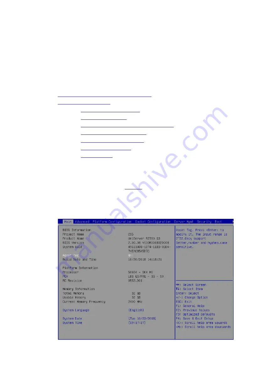
1. 

Access the BIOS. Press 

Delete

Esc

, or 

F2 

as prompted during server POST to open the 

BIOS setup screen as shown in


Figure 1

. For some servers, the 

Front Page

 screen opens, 

and you must select 

Device Management

 before proceeding to the next step. 

For how to navigate screens and modify settings, see the operation instructions at the lower 
right corner.   

Figure 1 BIOS setup screen 


Summary of Contents for UniServer E3200 G3

Page 1: ...H3C Servers Storage Controller User Guide New H3C Technologies Co Ltd http www h3c com Document version 6W107 20220725...

Page 2: ...New H3C Technologies Co Ltd any trademarks that may be mentioned in this document are the property of their respective owners Notice The information in this document is subject to change without notic...

Page 3: ...equired syntax choices separated by vertical bars from which you select one x y Square brackets enclose a set of optional syntax choices separated by vertical bars from which you select one or none x...

Page 4: ...s a Layer 2 or Layer 3 switch or a router that supports Layer 2 forwarding and other Layer 2 features Represents an access controller a unified wired WLAN module or the access controller engine on a u...

Page 5: ...Documentation feedback You can e mail your comments about product documentation to info h3c com We appreciate your comments...

Page 6: ...G 1Rx8 R S which have different suffixes Storage controllers provide powerful I O transmission and bandwidth processing capabilities and support various RAID expansions to improve system performance W...

Page 7: ...all RAID configuration scenarios H3C Servers Storage Controllers User Guide Configure RAID simultaneously when the OS is installed from the iFIST interface Yes Applicable to the scenario where iFIST...

Page 8: ...he following scenarios Use ARCCONF Command Line Utility to configure RAID with a PMC storage controller Use StorCLI to configure RAID with an LSI storage controller Use Intel VROC 6 0 PV GUI to config...

Page 9: ...mes a RAID member drive and the new drive is idle You can configure the new drive as a hot spare drive from the management interface or CLI Dedicated Spare Specifies a hot spare drive for a specific r...

Page 10: ...build feature is applicable to scenarios where automatic RAID rebuild is required after faulty drive replacement Copyback About copyback If a drive fails the storage controller uses a hot spare drive...

Page 11: ...he RAID capacity If needed the level of the RAID array can be migrated to accommodate the newly added drives Applicable scenarios You can perform RAID capacity expansion when the current RAID capacity...

Page 12: ...nformation clearing on drives About RAID information clearing If a drive is hot swapped RAID information remains on the drive You must clear RAID information on the drive before you configure the driv...

Page 13: ...annot be used to configure RAID arrays but can be identified by the OS Ready Drives in this state can be used to configure RAID arrays Optimal Drives in this state have been used for configuring RAID...

Page 14: ...available after the initialization is finished Applicable scenarios To make the member drives in the redundant RAID array meet the requirement of the RAID level you can use this feature Drive scanning...

Page 15: ...ive failure alarming When a storage controller detects a failing drive HDM generates an alarm and turns the Fault UID LED on the drive backplane to flashing amber When a storage controller detects a f...

Page 16: ...the server Applicable scenarios You can use this feature to replace drives without powering off the server RAID creation with NVMe drives About RAID creation with NVMe drives You can use Intel VROC or...

Page 17: ...n configure RAID in both UEFI mode and legacy mode Features Operating modes The RAID controller supports the following operating modes AHCI mode This is the default mode In this mode all physical driv...

Page 18: ...affected and maintenance complexities will increase Configuring RAID arrays in UEFI mode This section describes how to configure RAID arrays through an embedded RSTe RAID controller in UEFI mode For...

Page 19: ...Enter For G5 servers the Platform Configuration options are in the Advanced menu Figure 2 Platform Configuration screen 3 On the screen as shown in Figure 3 select PCH SATA Configuration or PCH sSATA...

Page 20: ...mation about setting the operating mode for an embedded RSTe RAID controller see Features Figure 4 Modifying the storage controller operating mode 5 After the configuration is complete press F4 On the...

Page 21: ...roller and press Enter NOTE For the Intel R VROC SATA Controller or Intel R VROC sSATA Controller option to appear on the screen shown in Figure 5 make sure the SATA or sSATA controller has been confi...

Page 22: ...er The Create RAID Volume option is available only when the interface corresponding to the SATA or sSATA controller connects to two or more drives Figure 7 Selecting Create RAID Volume 2 On the screen...

Page 23: ...rives are displayed under Select Disks Press Enter to select drives X indicates that the corresponding drive has been selected Strip Size Stripe size which determines the size of the data block that c...

Page 24: ...l is degraded due to drive failures hot spare drives replace the failed drives automatically The system starts RAID rebuilding automatically after accessing the OS 1 On the RSTe configuration screen a...

Page 25: ...drive 3 On the following screen that opens select Yes and press Enter Figure 12 Confirming the hot spare configuration Deleting RAID arrays 1 On the RSTe configuration screen as shown in Figure 13 se...

Page 26: ...e screen as shown in Figure 14 select Delete and press Enter to delete the selected RAID volume Figure 14 RAID volume information screen Locating a drive 1 On the RSTe configuration screen as shown in...

Page 27: ...the user guide for the server Figure 16 Locating a logical drive Initializing a logical drive The embedded RAID controller automatically initializes the RAID after RAID configuration After initializa...

Page 28: ...Setting the RSTe operating mode Accessing the RSTe configuration screen Configuring RAID arrays Optional Configuring hot spare drives Optional Deleting RAID arrays Setting the RSTe operating mode 1 A...

Page 29: ...ng the RSTe configuration screen This section describes how to access the legacy BIOS configuration screen To enter the RSTe configuration screen make sure a minimum of one embedded RSTe RAID controll...

Page 30: ...e sSATA controller and SATA controller Select a controller according to the drives to be configured for a RAID array The RSTe configuration screen as shown in Figure 21 opens Table 3 describes the con...

Page 31: ...t existing RAID arrays and physical drives Configuring RAID arrays 1 On the RSTe configuration screen as shown in Figure 22 select Create RAID Volume and press Enter Figure 22 RSTe configuration scree...

Page 32: ...for the RAID array To select a drive select Disks press Enter navigate to the drive and then press the space bar Strip Size Stripe size which determines the size of the data block that can be written...

Page 33: ...RAID rebuilding automatically after accessing the OS 1 On the RSTe configuration screen select Mark Disks as Spare and press Enter Figure 25 RSTe configuration screen 2 Select a drive for hot spare pr...

Page 34: ...leting RAID arrays 1 On the RSTe configuration screen as shown in Figure 28 select Delete RAID Volume and press Enter Figure 28 RSTe configuration screen 2 On the screen as shown in Figure 29 select t...

Page 35: ...19 Figure 29 Selecting the RAID volume to be deleted...

Page 36: ...cations of NVMe VROC modules supported by the server For more information contact Technical Support Table 1 NVMe VROC module specifications Model Description RAID levels N A No NVMe VROC module instal...

Page 37: ...ill increase Configuring RAID arrays in UEFI mode This section describes how to configure RAID arrays through an embedded RSTe RAID controller in UEFI mode For more information about how to enter the...

Page 38: ...e 2 select Socket Configuration IIO Configuration and press Enter For G5 servers the Socket Configuration options are in the Advanced menu Figure 2 Socket Configuration screen 3 On the screen as shown...

Page 39: ...s Enter This section takes processor 1 as an example Figure 4 Intel VMD technology screen 5 For G3 servers only On the screen as shown in Figure 5 set each Intel VMD for Volume Management Device for P...

Page 40: ...s Intel VMD the volume management device for PStackX The screen displays items for further configuration if you set the item to Enabled Auto Enables Intel VMD automatically when a device is detected f...

Page 41: ...MD for the port This field is available for a port only when a device is connected to the port The slot number varies by riser card and NVMe drive backplane Disabled Hot Plug Capable Select Enabled or...

Page 42: ...he VMD controllers have been enabled For how to enable VMD controllers see Configuring VMD settings Figure 7 Advanced screen 3 On the screen as shown in Figure 8 select All Intel VMD Controllers and t...

Page 43: ...able only when the NVMe VROC module identifies that a minimum of two non RAID NVMe drives are present Figure 10 Selecting Create RAID Volume 2 On the screen as shown in Figure 11 set the Name RAID Lev...

Page 44: ...hich determines the size of the data block that can be written into a stripe on each drive Select Disks Select member drives for the RAID array Available drives are displayed under Select Disks Press...

Page 45: ...rives 1 On the RAID configuration screen as shown in Figure 13 select the drive to be configured as a spare drive and press Enter Figure 13 Selecting the drive to be configured as a spare drive 2 On t...

Page 46: ...screen as shown in Figure 15 select Yes and press Enter Figure 15 Confirming the spare drive configuration Deleting RAID arrays 1 On the RAID configuration screen as shown in Figure 16 select the RAI...

Page 47: ...Selecting the RAID volume to be deleted 2 On the screen as shown in Figure 17 select Delete and press Enter Figure 17 RAID volume information screen 3 On the screen as shown in Figure 15 select Yes an...

Page 48: ...drive 1 On the RAID configuration screen as shown in Figure 16 select the RAID volume to be located under RAID Volumes and press Enter Figure 19 Selecting the NVMe drive to be located 2 On the screen...

Page 49: ...NVMe RAID configuration screen Configuring RAID arrays Optional Configuring hot spare drives Optional Deleting RAID arrays Configuring VMD settings For information about how to configure VMD settings...

Page 50: ...rsion field might vary by server model Figure 21 Verifying VMD status Configuring RAID arrays Prerequisites Make sure the number of NVMe drives meets the requirements for RAID configuration Execute th...

Page 51: ...ute the mdadm C dev md0 dev md imsm0 n 4 l 5 z 10G command to create a container as shown in Figure 24 Table 6 describes the parameters Figure 24 Creating a RAID array Table 7 Configuration parameters...

Page 52: ...ev nvme 1 3 n1 n 3 e imsm command to create a container as shown in Figure 26 The number of NVMe drives for creating the container is n 1 This section takes 3 as an example Figure 26 Creating a contai...

Page 53: ...ve RAID information on NVMe drives as shown in Figure 29 Figure 29 Deleting a RAID array Configuring RAID arrays in Windows RAID array configuration tasks at a glance To configure RAID arrays in Windo...

Page 54: ...ess Controller or none for NVMe drive information in the Storage controllers section For information about how to enable VMD for RAID configuration see Configuring VMD settings Figure 30 Verifying VMD...

Page 55: ...d a RAID level and then click Next as shown in Figure 23 Figure 32 Selecting a controller and a RAID level 3 Edit the RAID array name select NVMe drives and select whether to enable VMD controller spa...

Page 56: ...21 Figure 33 Editing RAID settings 4 Click the Create Volume button as shown in Figure 34 Figure 34 Confirming RAID creation 5 Click OK to complete the RAID creation...

Page 57: ...RAID volume The right pane displays the details about a RAID volume including RAID level strip size RAID status and number of NVMe drives Figure 36 Viewing the created RAID volume Configuring hot spa...

Page 58: ...es 3 In the dialog box that opens click Yes Figure 38 Confirming the configuration 4 Select the NVMe drive and verify that the drive has been configured as a hot spare drive successfully in the Disk P...

Page 59: ...ion Deleting RAID arrays 1 Open Intel VROC 6 0 PV GUI 2 Select the RAID array to be deleted and then click Delete volume as shown in Figure 40 Figure 40 Deleting a RAID array 3 In the dialog box that...

Page 60: ...25 Figure 41 Confirming the deletion 4 Verifying that the RAID array has been deleted by viewing the Volumes list as shown in Figure 42 Figure 42 Verifying the deletion...

Page 61: ...re exposed as raw drives Physical drives without system partitions are configured as simple volumes Simple Volume mode In this mode only non redundant RAID arrays with the simple volume level each con...

Page 62: ...ally replaces the failed drive and rebuilds the data of the failed drive The storage controller supports the following types of hot spare drives For more information about hot spare drive types see St...

Page 63: ...tializing drives Configuring RAID arrays Optional Configuring hot spare drives Optional Deleting RAID arrays Optional Uninitializing drives Optional Locating drives Optional Erasing drives Optional Re...

Page 64: ...setup screen 2 On the screen as shown in Figure 2 select Advanced PMC maxView Storage Manager and press Enter Figure 2 Advanced screen 3 On the screen as shown in Figure 3 select Scan For Controllers...

Page 65: ...the screen as shown in Figure 4 select Controller 0 PM8060 RAID and press Enter Figure 4 Selecting Controller 0 PM8060 RAID 5 The storage controller configuration screen as shown in Figure 5 opens Thi...

Page 66: ...o perform the following tasks Modify the storage controller operating mode View the storage controller configuration information Restore the default configuration for a storage controller Disk Utiliti...

Page 67: ...oller configuration screen 2 On the screen as shown in Figure 7 select Controller Configuration and press Enter Figure 7 Controller Settings screen 3 On the screen as shown in Figure 8 select Controll...

Page 68: ...ribes the storage controller operating modes Figure 9 Selecting a storage controller operating mode Table 3 Storage controller operating modes Operating mode Description RAID expose RAW All RAID funct...

Page 69: ...system Simple Volume In this mode only non redundant RAID arrays with the simple volume level each contains only one drive can be created RAID arrays with other RAID levels cannot be created Before se...

Page 70: ...e must be initialized before it can be used for creating a RAID array or configured as a hot spare drive To initialize drives 1 On the storage controller configuration screen as shown in Figure 12 sel...

Page 71: ...SUBMIT and press Enter Figure 14 Selecting drives 4 If the system prompts that the initiation will erase all array information from the selected drives and affect RAID arrays using these selected dri...

Page 72: ...g RAID arrays 1 On the storage controller configuration screen as shown in Figure 16 select Logical Device Configuration and press Enter Figure 16 Storage controller configuration screen 2 On the scre...

Page 73: ...the drive has been selected Then select PROCEED and press Enter A raw drive cannot be selected To configure a RAID array for the drive you must first initialize the drive For more information about in...

Page 74: ...and Create RAID via parameters select SUBMIT and press Enter to create the array Table 4 describes the configuration parameters Figure 20 Setting RAID parameters Table 4 Configuration parameters Para...

Page 75: ...s created Skip Init Establishes the RAID relationship immediately after the RAID array is created without clearing the data Build Verify Verifies the data for the drives after the RAID array is create...

Page 76: ...out the RAID array including the RAID array name RAID level and member drives as shown in Figure 23 Figure 23 RAID array information screen Configuring hot spare drives After configuring a RAID array...

Page 77: ...re 24 select Logical Device Configuration and press Enter Figure 24 Storage controller configuration screen 2 On the screen as shown in Figure 25 select Global Hotspares and press Enter Figure 25 Logi...

Page 78: ...ure 27 select the drives to be configured as global hot spare drives Enabled following a drive means that the drive has been selected Then select ADD and press Enter to configure the global hot spare...

Page 79: ...n the screen as shown in Figure 28 select the RAID array for which you want to configure dedicated hot spare drives and press Enter Figure 28 Selecting a RAID array 3 On the screen as shown in Figure...

Page 80: ...spare drives Enabled following a drive means that the drive has been selected Then select ADD and press Enter to configure the dedicated hot spare drives Figure 31 Selecting drives Deleting RAID array...

Page 81: ...configuration screen 2 On the screen as shown in Figure 33 select Manage Arrays and press Enter Figure 33 Logical Device Configuration screen 3 On the screen as shown in Figure 34 select the RAID arra...

Page 82: ...y to be deleted 4 On the screen as shown in Figure 35 select Delete Array and press Enter Figure 35 Selecting Delete Array 5 On the screen as shown in Figure 36 select PROCEED or SUBMIT and press Ente...

Page 83: ...rtitions After a drive in Ready state is uninitialized it returns to the raw state To uninitialize drives 1 On the storage controller configuration screen as shown in Figure 37 select Logical Device C...

Page 84: ...rives to be uninitialized Enabled following a drive means the drive has been selected Then select SUBMIT and press Enter to uninitialize the drives Figure 39 Selecting drives Locating drives 1 On the...

Page 85: ...n the screen as shown in Figure 41 select the drive to be operated and press Enter Figure 41 Selecting a drive 3 On the screen as shown in Figure 42 select an operation Identify Drive in this example...

Page 86: ...he drive Identify Drive Locate the drive With this operation performed for a drive the Fault UID LED on the drive backplane turns steady blue Write Cache Set the write cache for the drive 4 On the scr...

Page 87: ...rive failure do not perform any other operations during the drive erasing process To erase drives 1 On the storage controller configuration screen as shown in Figure 44 select Logical Device Configura...

Page 88: ...46 select the drives to be erased Enabled following a drive means that the drive has been selected Then select SUBMIT and press Enter Figure 46 Selecting the drives to be erased 4 On the screen as sh...

Page 89: ...storage controller 1 On the storage controller configuration screen as shown in Figure 48 select Controller Settings and press Enter Figure 48 Storage controller configuration screen 2 On the screen...

Page 90: ...the LED lighting policy After the storage controller configuration is restored to the default the LED lighting policy becomes IBPI which causes the LED to operate abnormally You must set the LED light...

Page 91: ...ng the storage controller firmware online 1 On the storage controller configuration screen as shown in Figure 52 select Administration and press Enter Figure 52 Storage controller configuration screen...

Page 92: ...reen as shown in Figure 54 select the device where the update file resides fs1 in this example and press Enter Figure 54 Selecting the device where the update file resides 4 On the screen as shown in...

Page 93: ...he update is complete press F4 On the dialog box that opens select Yes to reboot the device and make the update take effect Enabling RAID rebuilding If hot spare drives are not configured you can perf...

Page 94: ...onfiguration screen as shown in Figure 57 select Controller Settings and press Enter Figure 57 Storage controller configuration screen 2 On the screen as shown in Figure 58 select Controller Configura...

Page 95: ...the RAID P430 M1 and RAID P430 M2 storage controllers only by using ARCCONF commands For more information contact Technical Support Configuring RAID arrays in legacy mode This section describes how t...

Page 96: ...ves Optional Locating drives Optional Modifying storage controller settings Accessing the PMC RAID management screen 1 During server POST press Ctrl A when the screen as shown in Figure 60 opens Figur...

Page 97: ...ens and modify settings see the operation instructions at the bottom Figure 62 PMC RAID management screen Table 6 Configuration tasks Option Description Logical Device Configuration Select Logical Dev...

Page 98: ...Utilities Select Disk Utilities to perform the following tasks Format drives Locate physical drives Switching the storage controller operating mode 1 On the PMC RAID management screen as shown in Figu...

Page 99: ...ge controller operating modes and press Enter Figure 66 Selecting a storage controller operating mode Table 7 Storage controller operating modes Operating mode Description RAID expose RAW All RAID fun...

Page 100: ...the simple volume level each contains only one drive can be created RAID arrays with other RAID levels cannot be created Before setting this mode you must delete all RAID arrays and hot spare drives...

Page 101: ...ion A raw drive must be initialized before it is used for creating a RAID array or configured as a hot spare drive To initialize drives 1 On the PMC RAID management screen as shown in Figure 69 select...

Page 102: ...rive that you want to initialize and press Insert to select the drive Repeat this step to select more drives Then press Enter Figure 71 Selecting and initializing drives Configuring RAID arrays 1 On t...

Page 103: ...e 73 select Create Array and press Enter Figure 73 Logical Device Configuration screen 3 On the screen as shown in Figure 74 navigate to the drive to be configured for a RAID array and press Insert to...

Page 104: ...te RAID via parameters select Done and press Enter Table 8 describes the parameters Figure 75 Setting RAID parameters Table 8 Configuration parameters Parameter Description Array Type Select a RAID le...

Page 105: ...Create RAID via Select a method for initializing the RAID array 5 After the RAID array is created select Manage Arrays and press Enter on the screen as shown in Figure 76 Figure 76 Selecting Manage Ar...

Page 106: ...guring a logical drive as the first boot option Only a logical drive in Optimal state can be configured as the first boot option To configure a logical drive as the first boot option 1 On the PMC RAID...

Page 107: ...boot option Only a raw physical drive can be configured as the first boot option To configure a physical drive in any other state as the first boot option you must first perform the Uninitializing dr...

Page 108: ...d press Enter Figure 81 Logical Device Configuration screen 3 On the screen as shown in Figure 82 navigate to the drive to be used as the boot device press Insert to select the drive and press Enter F...

Page 109: ...screen 2 On the screen as shown in Figure 84 select Manage Arrays and press Enter Figure 84 Logical Device Configuration screen 3 On the screen as shown in Figure 85 select the RAID array to be delet...

Page 110: ...RAID hide RAW RAID expose RAW Auto Volume or Simple Volume Perform this task to clear data Adaptec metadata and reserved space on drives and remove the system partitions After a drive in Ready state...

Page 111: ...eat this step to select more drives Then press Enter to uninitialize the selected drives Figure 87 Selecting and uninitializing drives Erasing drives CAUTION To avoid data loss do not enter the operat...

Page 112: ...RAID management screen 2 On the screen as shown in Figure 89 select Secure Erase Drives and press Enter Figure 89 Logical Device Configuration screen 3 On the screen as shown in Figure 90 navigate to...

Page 113: ...the PMC RAID management screen as shown in Figure 91 select Disk Utilities and press Enter Figure 91 PMC RAID management screen 2 On the screen as shown in Figure 92 you can view the drive information...

Page 114: ...rating the drive Modifying storage controller settings Perform this task to view the storage controller configuration information restore the default configuration for the storage controller and modif...

Page 115: ...ttings screen 3 On the screen as shown in Figure 96 you can view or modify the basic configuration information for the storage controller Press F6 to restore the default configuration for the storage...

Page 116: ...56 Figure 96 Controller Configuration screen...

Page 117: ...is changed To resolve the issue re install the operating system If the issue persists contact Technical Support If the storage controller has RAID configuration you must clear RAID configuration befor...

Page 118: ...how to configure RAID arrays through a storage controller in UEFI mode For more information about how to enter the BIOS and set the boot mode to UEFI see the BIOS user guide for the server RAID array...

Page 119: ...setup screen 2 On the screen as shown in Figure 2 select Advanced Adaptec Smart IOC 8i and press Enter Figure 2 Selecting Adaptec Smart IOC 8i The storage controller configuration screen as shown in...

Page 120: ...ating mode 1 On the storage controller configuration screen as shown in Figure 4 select Configure Controller Settings and press Enter Figure 4 Storage controller configuration screen 2 On the screen a...

Page 121: ...drive backplane you can set different modes for connector CN0 and connector CN1 If the storage controller connects to an expander module specify the same operating mode for connector CN0 and connector...

Page 122: ...ring a RAID array 1 On the storage controller configuration screen as shown in Figure 8 select Array Configuration and press Enter Figure 8 Storage controller configuration screen 2 On the screen as s...

Page 123: ...ect the target drives Enabled following a drive means that the drive has been selected Then select Proceed to next Form and press Enter Figure 10 Selecting the target drives 4 On the screen as shown i...

Page 124: ...ack Size Unit Size SSD Over Provisioning Optimization and Acceleration Method Then select Submit Changes and press Enter For more information about the parameter description see Table 2 Figure 12 Conf...

Page 125: ...leration method 6 After creating the RAID array select Array Configuration Manage Arrays and press Enter On the screen as shown in Figure 13 select the RAID array you want to view and press Enter Figu...

Page 126: ...ls and press Enter to view detailed information about the RAID array including RAID array name level and drive information Figure 15 Selecting Logical Drive Details Configuring hot spare drives 1 On t...

Page 127: ...troller configuration screen 2 On the screen as shown in Figure 17 select Manage Arrays and press Enter Figure 17 Array Configuration screen 3 On the screen as shown in Figure 18 select the target RAI...

Page 128: ...t Manage Spare Drives and press Enter Figure 19 Selecting Manage Spare Drives 5 On the screen as shown in Figure 20 select Assign Dedicated Spare for specifying hot spare drives for the specified arra...

Page 129: ...lecting the target drive Deleting a RAID array This task allows you to delete a RAID array and the logical drives contained in it NOTE Deleting logical drives in the middle of a RAID array might cause...

Page 130: ...cal drives in the middle wait for all the logical drives to enter normal state before executing any other operations To delete a RAID array 1 On the storage controller configuration screen as shown in...

Page 131: ...On the screen as shown in Figure 25 select Delete Array and press Enter Figure 25 Selecting Delete Array Scanning drives and viewing drive information 1 On the storage controller configuration screen...

Page 132: ...an see information for all available drives Figure 27 Drive information Locating drives 1 Select the target drive on the screen as shown in Figure 27 and press Enter 2 On the screen as shown in Figure...

Page 133: ...r configuration screen as shown in Figure 29 select Controller Information and press Enter Figure 29 Storage controller configuration screen 2 On the screen as shown in Figure 30 you can see basic inf...

Page 134: ...scription Parameter Description Controller Storage controller model Hardware Revision Hardware version Viewing and modifying storage controller settings 1 On the storage controller configuration scree...

Page 135: ...elect Modify Controller Settings and press Enter Figure 32 Controller Configuration screen 3 On the screen as shown in Figure 33 you can view and modify the basic storage controller settings If no log...

Page 136: ...figuration information 1 On the storage controller configuration screen as shown in Figure 34 select Configure Controller Settings and press Enter Figure 34 Storage controller configuration screen 2 O...

Page 137: ...ion screen 3 On the screen as shown in Figure 36 select Delete All Arrays Configurations and press Enter Figure 36 Selecting Delete All Arrays Configurations 4 On the screen as shown in Figure 37 sele...

Page 138: ...grade the SEEPROM contact Technical Support To upgrade the storage controller firmware online 1 On the storage controller configuration screen as shown in Figure 38 select Administration and press Ent...

Page 139: ...3 On the screen as shown in Figure 40 select Proceed to next Form and press Enter Figure 40 Selecting Proceed to next Form 4 On the screen as shown in Figure 41 select the target device where the upda...

Page 140: ...device 5 On the screen as shown in Figure 42 select the update file suffixed with bin thor bin in this example and press Enter Figure 42 Selecting the update file 6 On the screen as shown in Figure 4...

Page 141: ...ffect Erasing drives 1 On the storage controller configuration screen as shown in Figure 44 select Disk Utilities and press Enter The system starts to scan all available drives Figure 44 Storage contr...

Page 142: ...the drive to be erased 3 On the screen as shown in Figure 46 select Erase Disk and press Enter Figure 46 Erasing a drive 4 On the screen as shown in Figure 47 press Enter to start erasing After erasi...

Page 143: ...To configure a RAID array in legacy mode perform the following tasks Accessing the storage controller configuration screen Switching the operating mode Configuring a RAID array Optional Configuring h...

Page 144: ...u can view basic RAID status and version information on the storage controller configuration screen Figure 49 Storage controller configuration screen Switching the operating mode 1 On the storage cont...

Page 145: ...n 2 On the screen as shown in Figure 51 select Configure Controller Port Mode and press Enter Figure 51 Configure Controller Settings screen 3 On the screen as shown in Figure 52 change the operating...

Page 146: ...uring a RAID array 1 On the storage controller configuration screen as shown in Figure 53 select Array Configuration and press Enter Figure 53 Storage controller configuration screen 2 On the screen a...

Page 147: ...it Repeat this step to select more drives and then press Enter Figure 55 Selecting the target drives 4 On the screen as shown in Figure 56 set the values for RAID Level Logical Drive Name Stripe Size...

Page 148: ...performance fault tolerance capability and logical drive capacity Logical Drive Name RAID array name Stripe Size Data block size for each drive Size Capacity of the logical drive Acceleration Method L...

Page 149: ...legacy mode if a hot spare drive is configured for a RAID array the hot spare drive will not take effect on other RAID arrays To avoid this problem configure all RAID arrays and then add hot spare dri...

Page 150: ...hown in Figure 61 select the target array and press Ctrl S Figure 61 Selecting the target array 4 On the screen as shown in Figure 62 navigate to a drive and press Insert or the space bar to select it...

Page 151: ...he spare type select Done and then press Enter Figure 63 Selecting the spare type Configuring the primary boot drives Configuring physical drives as the primary boot drives 1 On the storage controller...

Page 152: ...reen as shown in Figure 65 select Select Boot Device and press Enter Figure 65 Array Configuration screen 3 On the screen as shown in Figure 66 navigate to a drive and press Ctrl P or Ctrl S to select...

Page 153: ...ive 1 On the storage controller configuration screen select Array Configuration and press Enter 2 On the screen as shown in Figure 67 select Manage Arrays and press Enter Figure 67 Array Configuration...

Page 154: ...hown in Figure 69 press Ctrl P to configure the RAID array as the primary boot drive Figure 69 Configuring the primary boot drive Deleting a RAID array 1 On the storage controller configuration screen...

Page 155: ...ation screen 2 On the screen as shown in Figure 71 select Manage Arrays and press Enter Figure 71 Array Configuration screen 3 On the screen as shown in Figure 72 select the target array press Enter a...

Page 156: ...torage controller configuration screen as shown in Figure 73 select Disk Utilities and press Enter The storage controller starts scanning all available drives Figure 73 Storage controller configuratio...

Page 157: ...llowing operations Select Device Information and press Enter to view drive information Select Identify Drive and press Enter to locate the drive The Fault UID LED on the drive turns steady green Figur...

Page 158: ...figuration screen 2 On the screen as shown in Figure 77 select Modify Controller Settings and press Enter Figure 77 Configure Controller Settings screen 3 On the screen as shown in Figure 78 you can v...

Page 159: ...creen 4 Press F6 to restore the storage controller settings to the default NOTE The settings such as Transformation Priority and Rebuild Priority on the screen as shown in Figure 78 are configurable b...

Page 160: ...I 9460 8i 4G RAID LSI 9460 16i 4G RAID L460 M4 HBA H5408 Mf 8i RAID P5408 Mf 8i 4GB RAID P5408 Ma 8i 4GB RAID LSI 9560 LP 16i 8GB RAID LSI 9560 LP 8i 4GB HBA LSI 9540 LP 8i Features RAID levels The su...

Page 161: ...es in the RAID If you use one physical drive to create multiple RAIDs RAID performance might decrease in addition to increased maintenance complexities Configuring RAID arrays in UEFI mode This sectio...

Page 162: ...Page screen opens and you must select Device Management before proceeding to the next step For how to navigate screens and modify settings see the operation instructions at the lower right corner Figu...

Page 163: ...screen 3 Select Main Menu as shown in Figure 3 and press Enter Figure 3 Selecting Main Menu The storage controller configuration screen as shown in Figure 4 opens This screen contains five tasks as d...

Page 164: ...lowing tasks View and manage controller properties Clear schedule or run controller events Virtual Drive Management Select Virtual Drive Management to perform the following tasks View logical drive pr...

Page 165: ...a hot spare drive JBOD JBOD online Just a Bunch Of Disks The drive is a passthrough or passthrough like drive and does not support RAID configuration The passthrough drive is in JBOD online state by...

Page 166: ...3 On the screen as shown in Figure 7 select Operation and press Enter On the dialog box that appears select Make Unconfigured Bad and press Enter Figure 7 Operation screen 4 On the screen as shown in...

Page 167: ...on is complete the screen as shown in Figure 9 opens Figure 9 Completing drive state switchover Configuring a RAID array 1 On the storage controller configuration screen as shown in Figure 10 select C...

Page 168: ...tion screen 2 On the screen as shown in Figure 11 select Create Virtual Drive and press Enter Figure 11 Selecting Create Virtual Drive 3 On the screen as shown in Figure 12 select Select RAID Level to...

Page 169: ...et the drive capacity source and then press Enter Unconfigured Capacity The capacity source is the unconfigured drives Free Capacity The capacity source is the remaining drive capacity Figure 13 Setti...

Page 170: ...he drive has been selected Then select Apply Changes and press Enter A drive in JBOD or Unconfigured Bad status cannot be selected Figure 15 Selecting the target drives 7 On the screen as shown in Fig...

Page 171: ...he No Read Ahead Write Through and Direct values setting the Read Ahead Write Back and Cached values can improve performance but at the cost of losing data consistency Write Policy Write cache policy...

Page 172: ...e write process If this policy is used data will not get lost upon an unexpected power failure but the write performance will not as high as when drive caching is enabled Unchanged Uses the default dr...

Page 173: ...guration 9 On the screen as shown in Figure 18 select OK to return to the storage controller configuration screen Figure 18 Completing RAID array configuration 10 Select Virtual Drive Management and p...

Page 174: ...ee the created drives Select the drive you want to view and press Enter Figure 20 Virtual Drive Management screen 12 On the screen as shown in Figure 21 select View Associated Drives and press Enter Y...

Page 175: ...rives NOTE A hot spare drive can be used only for RAID levels with redundancy The capacity of a hot spare drive must be equal to or greater than the capacity of the smallest drive in the RAID array On...

Page 176: ...e screen as shown in Figure 23 select the target drive and press Enter Figure 23 Drive Management screen 3 On the screen as shown in Figure 24 select Operation and press Enter On the dialog box that a...

Page 177: ...screen as shown in Figure 25 select Go and press Enter Figure 25 Selecting Go 5 On the screen as shown in Figure 26 select Confirm and press Enter On the dialog box that opens select Enabled and press...

Page 178: ...is complete the screen as shown in Figure 27 opens Figure 27 Completing global hot spare drive configuration Configuring a dedicated hot spare drive 1 On the storage controller configuration screen a...

Page 179: ...screen as shown in Figure 29 select the target drive and press Enter Figure 29 Drive Management screen 3 On the screen as shown in Figure 30 select Operation and press Enter On the dialog box that ap...

Page 180: ...Figure 31 select Go and press Enter Figure 31 Selecting Go 5 On the screen as shown in Figure 32 select the drive you want to configure as the hot spare drive Enabled following the drive means that t...

Page 181: ...he operation is complete the screen as shown in Figure 33 opens Figure 33 Completing the operation Deleting a RAID array 1 On the storage controller configuration screen as shown in Figure 34 select V...

Page 182: ...creen as shown in Figure 35 select the target virtual drive and press Enter Figure 35 Virtual Drive Management screen 3 On the screen as shown in Figure 36 select Operation and press Enter On the dial...

Page 183: ...screen as shown in Figure 37 select Go and press Enter Figure 37 Selecting Go 5 On the screen as shown in Figure 38 select Confirm and press Enter On the dialog box that opens select Enabled and press...

Page 184: ...in Figure 39 opens Figure 39 Completing the operation Locating drives This task allows you to locate a physical drive or all drives for a virtual drive Locating a physical drive 1 On the storage contr...

Page 185: ...2 On the screen as shown in Figure 41 select the target drive and press Enter Figure 41 Selecting the target drive 3 On the screen as shown in Figure 42 select Operation and press Enter On the dialog...

Page 186: ...tion screen 4 On the screen as shown in Figure 43 select Go and press Enter Figure 43 Selecting Go When the operation is complete the screen as shown in Figure 44 opens The Fault UID LED on the drive...

Page 187: ...es for a virtual drive 1 On the storage controller configuration screen as shown in Figure 45 select Virtual Drive Management and press Enter Figure 45 Storage controller configuration screen 2 On the...

Page 188: ...drive 3 On the screen as shown in Figure 47 select Operation and press Enter On the dialog box that opens select Start Locate and press Enter Figure 47 Operation screen 4 On the screen as shown in Fi...

Page 189: ...wn in Figure 49 opens The Fault UID LED on the drive turns steady blue Figure 49 Completing locating all drives for a virtual drive Initializing a virtual drive This task allows you to initialize a vi...

Page 190: ...0 Storage controller configuration screen 2 On the screen as shown in Figure 51 select the target drive and press Enter Figure 51 Virtual Drive Management screen 3 On the screen as shown in Figure 52...

Page 191: ...on allows writing data after initialization is complete 4 On the screen as shown in Figure 53 select Go and press Enter Figure 53 Selecting Go 5 On the screen as shown in Figure 54 select Confirm and...

Page 192: ...hen the operation is complete the screen as shown in Figure 55 opens Figure 55 Completing the operation Initializing a physical drive 1 On the storage controller configuration screen as shown in Figur...

Page 193: ...2 On the screen as shown in Figure 57 select the target drive and press Enter Figure 57 Drive Management screen 3 On the screen as shown in Figure 58 select Operation and press Enter On the dialog bo...

Page 194: ...screen as shown in Figure 59 select Go and press Enter Figure 59 Selecting Go 5 On the screen as shown in Figure 60 select Confirm and press Enter On the dialog box that opens select Enabled and press...

Page 195: ...is complete the screen as shown in Figure 61 opens Figure 61 Completing the operation Erasing drives CAUTION To avoid drive failure do not perform other operations when erasing a physical drive This t...

Page 196: ...ration screen 2 On the screen as shown in Figure 63 select the target drive and press Enter Figure 63 Drive Management screen 3 On the screen as shown in Figure 64 select Operation and press Enter 4 O...

Page 197: ...ion screen 5 On the screen as shown in Figure 65 press Enter and set the Erase Mode the default Simple mode is recommended Figure 65 Setting the Erase Mode 6 On the screen as shown in Figure 66 select...

Page 198: ...hown in Figure 67 select Confirm and press Enter On the dialog box that opens select Enabled and press Enter Then select Yes and press Enter Figure 67 Confirming the operation When the operation is co...

Page 199: ...l drive 1 On the storage controller configuration screen as shown in Figure 69 select Virtual Drive Management and press Enter Figure 69 Storage controller configuration screen 2 On the screen as show...

Page 200: ...shown in Figure 71 select Operation and press Enter On the dialog box that appears select Virtual Drive Erase and press Enter Figure 71 Operation screen 4 On the screen as shown in Figure 72 press Ent...

Page 201: ...he screen as shown in Figure 73 select Go and press Enter Figure 73 Selecting Go 6 On the screen as shown in Figure 74 select Confirm and press Enter On the dialog box that opens select Enabled and pr...

Page 202: ...ete the screen as shown in Figure 75 opens Figure 75 Completing the operation Expanding a RAID array This task allows you to expand the RAID array capacity by setting the percentage of available logic...

Page 203: ...er Figure 76 Storage controller configuration screen 2 On the screen as shown in Figure 77 select the target drive and press Enter Figure 77 Virtual Drive Management screen 3 On the screen as shown in...

Page 204: ...creen 4 On the screen as shown in Figure 79 select Go and press Enter Figure 79 Selecting Go 5 On the screen as shown in Figure 80 modify the value for Enter a Percentage of Available Capacity select...

Page 205: ...n Figure 81 opens Figure 81 Completing expanding a RAID array Migrating the RAID level This task allows you to change the RAID level without affecting data integrity To migrate the RAID level 1 On the...

Page 206: ...screen as shown in Figure 83 select the target drive and press Enter Figure 83 Virtual Drive Management screen 3 On the screen as shown in Figure 84 select Operation and press Enter On the dialog box...

Page 207: ...4 Operation screen 4 On the screen as shown in Figure 85 select Go and press Enter Figure 85 Selecting Go 5 On the screen as shown in Figure 86 set the RAID level select Choose the Operation and then...

Page 208: ...es Enabled following a drive means that the drive has been selected Then select Apply Changes and press Enter Figure 87 Adding drives 7 On the screen as shown in Figure 88 select Confirm and press Ent...

Page 209: ...88 Confirming the operation 8 On the screen as shown in Figure 89 select Start Operation and then press Enter Figure 89 Start the operation 9 On the screen as shown in Figure 90 select OK and then pr...

Page 210: ...rmation on the drive This task allows you to clear remaining RAID array information on the drive for reconfiguring RAID array on the drive The task typically applies to drives in Unconfigured Bad stat...

Page 211: ...ement and press Enter Figure 92 Storage controller configuration screen 3 On the screen as shown in Figure 93 select Manage Foreign Configuration and press Enter Figure 93 Selecting Manage Foreign Con...

Page 212: ...e screen as shown in Figure 95 select Confirm and press Enter On the dialog box that opens select Enabled and press Enter Then select Yes and press Enter Figure 95 Confirming the operation When the op...

Page 213: ...e to avoid unintentional deletion To hide a virtual drive 1 On the storage controller configuration screen as shown in Figure 97 select Virtual Drive Management and press Enter Figure 97 Storage contr...

Page 214: ...press Enter On the dialog box that appears select Hide Virtual Drive and press Enter Figure 99 Operation screen Hiding a RAID array This task allows you to hide a RAID array to avoid unintentional del...

Page 215: ...ter Figure 100 Storage controller configuration screen 2 On the screen as shown in Figure 101 select the target drive and press Enter Figure 101 Virtual Drive Management screen 3 On the screen as show...

Page 216: ...irmware file in the root directory or a level 1 folder of the USB drive To upgrade the storage controller firmware online 1 On the Advanced screen as shown in Figure 103 select Update Firmware and pre...

Page 217: ...electing directory 3 On the screen as shown in Figure 105 select the image file of the target firmware and press Enter Figure 105 Selecting image 4 On the screen as shown in Figure 106 select Update a...

Page 218: ...lect Enabled and press Enter Then select Yes and press Enter CAUTION After confirming the upgrade the screen is stuck for a short time during which the firmware is being upgraded Do not perform any ot...

Page 219: ...60 Figure 108 Completing the operation 7 Restart the BIOS for the operation to take effect Switching the storage controller mode 1 On the Advanced menu select Main Menu and press Enter...

Page 220: ...61 Figure 109 Selecting Main Menu 2 Select Controller Management and press Enter...

Page 221: ...2 Figure 110 Selecting Controller Management 3 Select Advanced Controller Management and press Enter Figure 111 Selecting Advanced Controller Management 4 Select Manage Personality Mode and press Ente...

Page 222: ...igure 113 the storage controller is now is RAID mode To switch the controller to JBOD mode select Switch to JBOD Mode and press Enter Figure 113 Switching the controller to JBOD mode 5 Select Confirm...

Page 223: ...Confirming the mode switching 6 Select OK and press Enter to reboot the operating system for the change to take effect Figure 115 Completing the mode switching Configuring RAID arrays in legacy mode T...

Page 224: ...al Locating drives Optional Initializing a virtual drive Optional Erasing drives Optional Expanding a RAID array Optional Clearing RAID array information on the drive Optional Configuring boot options...

Page 225: ...on it If the drive is faulty replace the drive If the drive has RAID array information remaining on it clear the information JBOD Just a Bunch Of Drives The drive is a passthrough drive and does not...

Page 226: ...red good Configuring a RAID array 1 On the VD Mgmt screen as shown in Figure 120 press F2 and select Create Virtual Drive Figure 120 Selecting Create Virtual Drive 2 On the screen as shown in Figure 1...

Page 227: ...ID level 3 On the screen as shown in Figure 122 select the target drive and press Enter Figure 122 Selecting the target drive 4 On the screen as shown in Figure 123 specify the size and name select Ad...

Page 228: ...as shown in Figure 124 configure the parameters select OK and then press Enter For more information about the parameter description see Table 3 Figure 124 Configuring advanced RAID array parameters 6...

Page 229: ...on Configuring hot spare drives For data security purposes configure hot spare drives after configuring a RAID array You can configure a global hot spare drive or dedicated hot spare drive NOTE A hot...

Page 230: ...e target drive and press F2 Figure 127 Selecting the target drive 2 On the screen as shown in Figure 128 select Make Global HS and press Enter Figure 128 Selecting Make Global HS 3 On the screen as sh...

Page 231: ...the VD Mgmt screen press F2 and then select Manage Ded SH 2 On the screen as shown in Figure 130 select the target drive select Advanced and then press Enter Figure 130 Selecting the target virtual d...

Page 232: ...re 4 On the screen as shown in Figure 132 select the target drive select OK and then press Enter Figure 132 Selecting the target drive Deleting a RAID array 1 On the VD Mgmt screen as shown in Figure...

Page 233: ...gure 133 Selecting the target drive 2 On the screen as shown in Figure 134 select Delete VD and press Enter Figure 134 Selecting Delete VD 3 On the screen as shown in Figure 135 select YES and press E...

Page 234: ...drive To locate drives 1 On the PD Mgmt screen as shown in Figure 136 select the target drive and press F2 Figure 136 Selecting the target drive 2 On the screen as shown in Figure 137 select Locate S...

Page 235: ...to initialize a virtual drive to be used by operating systems To initialize a virtual drive 1 On the VD Mgmt screen as shown in Figure 138 select the target drive and press F2 Figure 138 Selecting th...

Page 236: ...e RAID array space Data write operations can be performed only when the initialization is complete 3 On the screen as shown in Figure 140 select YES and press Enter Figure 140 Confirming the operation...

Page 237: ...arget drive 2 On the screen as shown in Figure 142 select the erase mode the default Simple mode is recommended and press Enter Figure 142 Selecting the erase mode 3 On the screen as shown in Figure 1...

Page 238: ...ogical drive 1 On the VD Mgmt screen as shown in Figure 144 select the target drive and press F2 Figure 144 Selecting the target drive 2 On the screen as shown in Figure 145 select the erase mode the...

Page 239: ...ss Enter Figure 146 Confirming the operation Expanding a RAID array This task allows you to expand the RAID array capacity by setting the percentage of available capacity for logical drives To expand...

Page 240: ...screen as shown in Figure 148 select Expand VD size and press Enter Figure 148 Selecting Expand VD size 3 On the screen as shown in Figure 149 modify the value for Enter a percentage of available capa...

Page 241: ...ar RAID array information on the drive 1 Switch the drive state from Unconfigured Bad to Unconfigured Good For more information see Switching the drive state 2 On the Foreign View screen as shown in F...

Page 242: ...g boot options 1 On the Ctrl Mgmt screen as shown in Figure 152 select the target physical drive or logical drive as the boot device and then press Enter Figure 152 Selecting the boot device 2 Select...

Page 243: ...84 Figure 153 Confirming the operation...

Page 244: ...D functions are disabled RAID mode In this mode RAID functions are enabled and RAID arrays can be created on physical drives Only logical drives are exposed to the operating system Mixed mode This is...

Page 245: ...RAID 60 array Hot spare drives You can configure hot spare drives to improve data security A hot spare drive is a standby drive that does not store any data When a drive in a redundant RAID fails a sp...

Page 246: ...ng a RAID array Optional Viewing drive information Optional Locating drives Optional Erasing drives Optional Viewing basic storage controller information Optional Modifying storage controller settings...

Page 247: ...as shown in Figure 2 select Advanced storage controller model and press Enter In this example the storage controller model is UN HBA H460 B1 Figure 2 Selecting UN HBA H460 B1 The storage controller co...

Page 248: ...ch the operating mode 1 On the storage controller configuration screen as shown in Figure 4 select Configure Controller Settings and press Enter Figure 4 Storage controller configuration screen 2 On t...

Page 249: ...t CN0 Mode or Port CN1 Mode as a best practice make sure their operating modes are the same select Submit Changes and press Enter Figure 6 Modify Controller Settings screen Figure 6 shows a screen wit...

Page 250: ...ring a RAID array 1 On the storage controller configuration screen as shown in Figure 8 select Array Configuration and press Enter Figure 8 Storage controller configuration screen 2 On the screen as s...

Page 251: ...ect the target drives Enabled following a drive means that the drive has been selected Then select Proceed to next Form and press Enter Figure 10 Selecting the target drives 4 On the screen as shown i...

Page 252: ...t Size and Acceleration Method Then select Submit Changes and press Enter For more information about the parameter description see Table 2 Figure 12 Configuring RAID array parameters Table 2 Parameter...

Page 253: ...Array Configuration Manage Arrays and press Enter On the screen as shown in Figure 13 that opens select the RAID array you want to view and press Enter Figure 13 Selecting a RAID array 7 On the scree...

Page 254: ...s Enter Figure 15 Selecting Logical Drive 2 9 On the screen as shown in Figure 16 select Logical Drive Details and press Enter to view detailed information about the RAID array including RAID array na...

Page 255: ...Figure 17 select Array Configuration and press Enter Figure 17 Storage controller configuration screen 2 On the screen as shown in Figure 18 select Manage Arrays and press Enter Figure 18 Array Config...

Page 256: ...nage Spare Drives and press Enter Figure 20 Selecting Manage Spare Drivers 5 On the screen as shown in Figure 21 select Assign Dedicated Spare for specifying a hot spare drive for the specified array...

Page 257: ...ct the target drives Enabled following a drive means that the drive has been selected Then select Assign Dedicated Spare and press Enter Figure 22 Selecting the target drives Deleting a RAID array Thi...

Page 258: ...ols As a best practice to avoid these problems delete logical drives from back to front in sequence If you delete logical drives in the middle wait for all the logical drives to enter normal state bef...

Page 259: ...rray Configuration screen 3 On the screen as shown in Figure 25 select the target array and press Enter Figure 25 Selecting the target array 4 On the screen as shown in Figure 26 select Delete Array a...

Page 260: ...mation 1 On the storage controller configuration screen as shown in Figure 27 select Disk Utilities and press Enter Figure 27 Storage controller configuration screen 2 On the screen as shown in Figure...

Page 261: ...gure 28 and press Enter 2 On the screen as shown in Figure 29 select Identify Device and press Enter Figure 29 Selecting Identify Device 3 On the screen as shown in Figure 30 select Start and the Faul...

Page 262: ...RAID mode You can erase only physical drives To avoid drive failure do not power off restart or remove the drive during the erasing process Procedure 1 On the storage controller configuration screen a...

Page 263: ...31 Erasing a drive 3 On the screen as shown in Figure 32 select the erase pattern and press Enter Figure 32 Selecting the erase pattern 4 On the screen as shown in Figure 33 select Start Erase and pr...

Page 264: ...r configuration screen as shown in Figure 34 select Controller Information and press Enter Figure 34 Storage controller configuration screen 2 On the screen as shown in Figure 35 you can see basic inf...

Page 265: ...Description Controller Storage controller model Hardware Revision Hardware version Modifying storage controller settings 1 On the storage controller configuration screen as shown in Figure 36 select...

Page 266: ...er Figure 37 Configure Controller Settings screen 3 On the screen as shown in Figure 38 modify the basic storage controller settings as needed If no logical drives are available you can only modify th...

Page 267: ...on screen as shown in Figure 39 select Configure Controller Settings and press Enter Figure 39 Storage controller configuration screen 2 On the screen as shown in Figure 40 or Figure 41 select Clear C...

Page 268: ...controllers support the Backup Power Source option This option indicates that the controllers can provide power fail safeguard if it has a supercapacitor connected 3 On the screen as shown in Figure...

Page 269: ...grade the SEEPROM contact Technical Support To upgrade the storage controller firmware online 1 On the storage controller configuration screen as shown in Figure 44 select Administration and press Ent...

Page 270: ...screen as shown in Figure 46 select Select Firmware File to flash and press Enter Figure 46 Selecting Select Firmware File to flash 4 On the screen as shown in Figure 47 select the target device where...

Page 271: ...On the screen as shown in Figure 48 select the update file suffixed with bin luxor bin in this example and press Enter Figure 48 Selecting the update file 6 On the screen as shown in Figure 49 select...

Page 272: ...the BIOS user guide for the server RAID array configuration tasks at a glance To configure RAID arrays in legacy mode perform the following tasks Accessing the storage controller configuration screen...

Page 273: ...configuration screen opens as shown in Figure 51 You can view basic RAID array status and version information on the storage controller configuration screen Figure 51 Storage controller configuration...

Page 274: ...screen 2 On the screen as shown in Figure 53 select Configure Controller Port Mode and press Enter Figure 53 Configure Controller Settings screen 3 On the screen as shown in Figure 54 change the oper...

Page 275: ...uring a RAID array 1 On the storage controller configuration screen as shown in Figure 55 select Array Configuration and press Enter Figure 55 Storage controller configuration screen 2 On the screen a...

Page 276: ...at this step to add more drives and press Enter Figure 57 Selecting the target drive 4 On the screen as shown in Figure 58 set the values for RAID Level Logical Drive Name Strip Full Stripe Size Parit...

Page 277: ...ve capacity Logical Drive Name RAID array name Strip Full Stripe Size Data block size for each drive Parity Group Count Number of RAID 1 or RAID 5 groups used to create RAID 10 or RAID 50 Build Method...

Page 278: ...n Figure 60 Selecting the target RAID array Configuring hot spare drives Restrictions and guidelines In legacy mode if a hot spare drive is configured for a RAID array the hot spare drive will not tak...

Page 279: ...ontroller configuration screen 2 On the screen as shown in Figure 62 select Manage Arrays and press Enter Figure 62 Array Configuration screen 3 On the screen as shown in Figure 63 select the target a...

Page 280: ...Figure 64 navigate to the target drive and press Insert or the space bar to select it Repeat this step to add more drives and press Enter Figure 64 Selecting the target drives 5 On the screen as shown...

Page 281: ...physical drive as the primary boot drive 1 On the storage controller configuration screen as shown in Figure 66 select Array Configuration and press Enter Figure 66 Storage controller configuration s...

Page 282: ...rive press Ctrl P and then press Enter Figure 68 Selecting the target drive Configuring a logical drive as the primary boot drive 1 On the storage controller configuration screen select Array Configur...

Page 283: ...reen 3 On the screen as shown in Figure 70 select the target RAID array and press Enter Figure 70 Selecting the target RAID array 4 On the screen as shown in Figure 71 press Ctrl P to configure the RA...

Page 284: ...ng a RAID array 1 On the storage controller configuration screen as shown in Figure 72 select Array Configuration and press Enter Figure 72 Storage controller configuration screen 2 On the screen as s...

Page 285: ...n in Figure 74 select the target array press Enter and then press Delete to delete the array Figure 74 Deleting the target array Viewing drive information 1 On the storage controller configuration scr...

Page 286: ...can see information about all available drives Figure 76 Drive information Locating drives 1 Select the target drive on the screen as shown in Figure 76 and press Enter 2 On the screen as shown in Fi...

Page 287: ...e controller configuration screen as shown in Figure 76 select the drive to be erased and then press Enter 2 On the screen as shown in Figure 78 select Secure Erase and then press Enter Figure 78 Eras...

Page 288: ...ttings 1 On the storage controller configuration screen as shown in Figure 80 select Configure Controller Settings and press Enter Figure 80 Storage controller configuration screen 2 On the screen as...

Page 289: ...torage controller settings Figure 82 Modify Controller Settings screen 4 Press F6 to restore the storage controller settings to the default NOTE The settings such as Transformation Priority and Rebuil...

Page 290: ...iew the status of the installed backup power source if any To display backup power source status 1 On the storage controller configuration screen as shown in Figure 83 select Configure Controller Sett...

Page 291: ...eld is fixed to Not Present Clearing storage controller configuration 1 On the storage controller configuration screen as shown in Figure 86 select Configure Controller Settings and press Enter Figure...

Page 292: ...Figure 88 select Delete All Array Configurations and press Enter In the confirmation dialog box that opens select Yes and press Enter Figure 88 Clearing storage controller configuration The screen as...

Page 293: ...50 Figure 89 Clearing completion...

Page 294: ...S user guide for the server Controller configuration tasks at a glance To configure the storage controller settings in UEFI mode perform the following tasks Accessing the controller configuration scre...

Page 295: ...submenu Select Advanced LSI SAS3 MPT Controller SAS3008 and press Enter Figure 2 Advanced screen 3 On the screen as shown in Figure 3 select LSI SAS3 MPT Controller and press Enter In this example th...

Page 296: ...Controller configuration screen View basic controller properties 1 Access the controller configuration screen For more information about how to access the controller configuration screen see Accessin...

Page 297: ...the screen as shown in Figure 6 select View Controller Properties and press Enter Figure 6 Selecting View Controller Properties 4 View the controller properties on the screen as shown in Figure 7 Tab...

Page 298: ...e storage controller Host interface Host interface type Changing controller properties 1 Access the controller configuration screen For more information about how to access the controller configuratio...

Page 299: ...ler configuration screen 3 On the screen as shown in Figure 9 select Change Controller Properties and press Enter Figure 9 Selecting Change Controller Properties 4 On the screen as shown in Figure 10...

Page 300: ...Access the controller configuration screen For more information about how to access the controller configuration screen see Accessing the controller configuration screen 2 On the screen as shown in F...

Page 301: ...ecting View Physical Disk Properties 4 On the screen as shown in Figure 13 select Select Physical Disk On the pop up window that opens select the physical drive you want to view and press Enter Figure...

Page 302: ...t how to access the controller configuration screen see Accessing the controller configuration screen 2 On the screen as shown in Figure 15 select Physical Disk Management and press Enter Figure 15 Co...

Page 303: ...17 Selecting a physical drive 5 Select Start Locate Blink and press Enter 6 On the server identify the physical drive of which the Fault UID LED is steady blue Configuring controller settings in legac...

Page 304: ...s Optional Locating drives Optional Verifying Formatting drives Optional Setting advanced controller properties Optional Configuring boot options Accessing the controller configuration screen 1 During...

Page 305: ...onfiguration screen For more information about how to access the controller configuration screen see Accessing the controller configuration screen 2 On the screen as shown in Figure 21 select SAS Topo...

Page 306: ...igure 23 Figure 23 Drive properties Locating drives 1 Access the controller configuration screen For more information about how to access the controller configuration screen see Accessing the controll...

Page 307: ...on the drive LED on the drive backplane Figure 25 Selecting a physical drive Verifying Formatting drives 1 Access the controller configuration screen For more information about how to access the cont...

Page 308: ...screen 3 On the screen as shown in Figure 27 select the physical drive you want to locate and press Alt D Figure 27 Selecting a physical drive 4 On the screen as shown in Figure 28 select Verify or F...

Page 309: ...more information about how to access the controller configuration screen see Accessing the controller configuration screen 2 On the screen as shown in Figure 29 select Advanced Adapter Properties and...

Page 310: ...roperties of the controller on the screen as shown in Figure 31 Figure 31 Advanced controller properties screen 5 Keep pressing Esc till you enter the screen as shown in Figure 32 Select Save changes...

Page 311: ...ng boot options 1 On the screen as shown in Figure 33 select SAS Topology and press Enter Figure 33 SAS Topology screen 2 On the screen as shown in Figure 34 select the target drive and then press Alt...

Page 312: ...ice select the drive and then press Alt B 4 Press Esc until the screen as shown in Figure 35 opens select Save changes then exit this menu and then press Enter The boot option configuration takes effe...

Page 313: ...re drives You can configure hot spare drives to improve data security A hot spare drive is a standby drive that does not store any data When a drive in a redundant RAID fails a spare drive automatical...

Page 314: ...spare drives Optional Deleting a RAID array Optional Clearing RAID array information on the drive Optional View basic controller properties Optional Changing controller properties Optional Viewing dri...

Page 315: ...MPT Controller SAS3008 and press Enter Figure 2 Advanced screen 3 On the screen as shown in Figure 3 select LSI SAS3 MPT Controller Version 18 00 00 00 and press Enter Figure 3 Selecting the LSI SAS3...

Page 316: ...RAID array 1 On the storage controller configuration screen as shown in Figure 5 select Controller Management and press Enter Figure 5 Storage controller configuration screen 2 On the screen as shown...

Page 317: ...al Drive 3 On the screen as shown in Figure 7 select Select RAID Level to set the RAID level and then press Enter Figure 7 Setting the RAID level 4 On the screen as shown in Figure 8 select Select Phy...

Page 318: ...Enabled following a drive means that the drive has been selected Then select Apply Changes and press Enter Figure 9 Selecting the target drives 6 On the screen as shown in Figure 10 select Confirm and...

Page 319: ...iguration 7 On the screen as shown in Figure 11 select OK to return to the storage controller configuration screen Figure 11 Completing RAID array configuration 8 Select Virtual Disk Management and pr...

Page 320: ...13 select Manage Virtual Disk Properties and press Enter Figure 13 Virtual Drive Management screen 10 On the screen as shown in Figure 14 select View Associated Drives and press Enter You can view th...

Page 321: ...drives 1 On the storage controller configuration screen as shown in Figure 15 select Virtual Disk Management and press Enter Figure 15 Storage controller configuration screen 2 On the screen as shown...

Page 322: ...ect Manage Global Hotspare Disks and press Enter Figure 17 Selecting Manage Global Hotspare Disks 4 On the screen as shown in Figure 18 select the target drives Enabled following a drive means that th...

Page 323: ...y 1 On the storage controller configuration screen as shown in Figure 19 select Virtual Disk Management and press Enter Figure 19 Storage controller configuration screen 2 On the screen as shown in Fi...

Page 324: ...shown in Figure 21 select Delete Virtual Disk and press Enter Figure 21 Selecting Delete Virtual Disk 4 On the screen as shown in Figure 22 select Confirm and press Enter On the dialog box that opens...

Page 325: ...peration Clearing RAID array information on the drive This task allows you to clear remaining RAID array information on the drive for reconfiguring RAID array on the drive To clear RAID array informat...

Page 326: ...ion screen 2 On the screen as shown in Figure 25 select Manage Foreign Configuration and press Enter Figure 25 Selecting Manage Foreign Configuration 3 On the screen as shown in Figure 26 select Clear...

Page 327: ...nfirm and press Enter On the dialog box that opens select Enabled and press Enter Then select Yes and press Enter Figure 27 Confirming the operation View basic controller properties 1 On the storage c...

Page 328: ...On the screen as shown in Figure 29 select View Controller Properties and press Enter Figure 29 Selecting View Controller Properties 3 View the controller properties on the screen as shown in Figure...

Page 329: ...Parameter Description Chip Revision Version of the chip Host interface Host interface type Persistent NVData Version Current NVData version Changing controller properties 1 On the storage controller...

Page 330: ...On the screen as shown in Figure 32 select Change Controller Properties and press Enter Figure 32 Selecting Change Controller Properties 3 On the screen as shown in Figure 33 change the controller se...

Page 331: ...n Rebuild Rate Percentage of I O resources occupied by RAID rebuild when a new hard drive is installed or a failed hard disk is replaced with a hot spare disk Viewing drive properties 1 On the storage...

Page 332: ...wn in Figure 36 select View Physical Disk Properties and press Enter Figure 36 Selecting View Physical Disk Properties 3 On the screen as shown in Figure 37 select Select Physical Disk On the pop up w...

Page 333: ...e on the screen as shown in Figure 38 You can select View More Physical Disk Properties for more information Figure 38 Viewing drive properties Locating drives 1 On the storage controller configuratio...

Page 334: ...wn in Figure 40 select Select Physical Disk Operations and press Enter Figure 40 Selecting physical disk operations 3 On the screen as shown in Figure 41 select Select Physical Disk On the pop up wind...

Page 335: ...ay configuration tasks at a glance To configure RAID arrays in legacy mode perform the following tasks Accessing the controller configuration screen Configuring a RAID array Optional Configuring hot s...

Page 336: ...24 Figure 42 Legacy BIOS setup screen 2 On the screen as shown in Figure 43 press Enter Figure 43 Main screen The controller configuration screen as shown in Figure 44 opens...

Page 337: ...port Support for storage controller management Options include Enabled BIOS OS RAID array management is supported for both the BIOS and the OS Enabled BIOS Only RAID array management is supported for...

Page 338: ...gure 46 select a target RAID level and press Enter Figure 46 Logical Device Configuration screen 3 On the screen as shown in Figure 47 navigate to a drive and then press the space bar to select the dr...

Page 339: ...shown in Figure 48 select Save changes then exit this menu and press Enter Figure 48 Save the controller configuration Configuring hot spare drives 1 On the storage controller configuration screen as...

Page 340: ...Table 4 RAID parameters Parameter Description Volume RAID serial number Identifier RAID identifier Type RAID level Status Current RAID status Task Current RAID task No background task is in progress f...

Page 341: ...Hot Spares 4 On the screen as shown in Figure 52 navigate to a drive and then press the space bar to select the drive Yes indicates that the drive has been selected Then press C Figure 52 Selecting th...

Page 342: ...eting a RAID array 1 On the storage controller configuration screen as shown in Figure 54 select RAID Properties and press Enter Figure 54 Storage controller configuration screen 2 On the screen as sh...

Page 343: ...Y to delete the array Figure 55 Deleting the target array Running consistency check This feature enables you to check the consistency and validity of data redundancy for RAID 1 10 and 1E To run consis...

Page 344: ...oller configuration screen 2 On the screen as shown in Figure 57 select Manage Volume and press Enter Figure 57 Selecting Manage Volume 3 On the screen as shown in Table 6 select Consistency Check pre...

Page 345: ...oller configuration screen as shown in Figure 58 select SAS Topology and press Enter Figure 58 Storage controller configuration screen 2 On the screen as shown in Figure 59 select the physical drive y...

Page 346: ...modes This field varies by RAID level and might display value such as RAID1 VOL or RAID10 VOL Alt D Displays the details if you select a drive that is highlighted on the screen Alt M Displays more ke...

Page 347: ...ct the physical drive you want to locate and press Enter to turn on the drive LED on the drive backplane Figure 62 Selecting a physical drive Clearing RAID information or verifying drives 1 On the sto...

Page 348: ...tion screen 2 On the screen as shown in Figure 64 select the physical drive you want to locate and press Alt D Figure 64 Selecting a physical drive 3 On the screen as shown in Figure 65 select Verify...

Page 349: ...roller properties 1 On the storage controller configuration screen as shown in Figure 66 select Advanced Adapter Properties and press Enter Figure 66 Storage controller configuration screen 2 On the s...

Page 350: ...troller on the screen as shown in Figure 68 Figure 68 Advanced controller properties screen 4 Keep pressing Esc till you enter the screen as shown in Figure 69 Select Save changes then exit this menu...

Page 351: ...age controller configuration screen as shown in Figure 70 select SAS Topology and then press Enter Figure 70 Storage controller configuration screen 2 On the screen as shown in Figure 71 select the ta...

Page 352: ...Configure or cancel a selected device as the secondary boot option The key changes to Boot in Device Info if the operation succeeds Alt B Configure or cancel a selected device as the first boot option...

Page 353: ...the screen as shown in Figure 73 select Save changes then exit this menu and then press Enter to save the configuration The boot option configuration takes effect at next startup Figure 73 Saving sto...

Page 354: ...formation about how to enter the BIOS and set the boot mode to UEFI see the BIOS user guide for the server Controller configuration tasks at a glance To configure controller settings in UEFI mode perf...

Page 355: ...igure 2 select Advanced Storage controller and press Enter In this example storage controller HBA 9400 8i is selected Figure 2 Advanced screen 3 On the storage controller configuration screen as shown...

Page 356: ...uration screen 4 On the confirmation screen as shown in Figure 4 select OK and then press Enter Figure 4 Confirming the operation 5 On the screen as shown in Figure 5 select OK and then press Enter to...

Page 357: ...on 1 On the storage controller configuration screen as shown in Figure 6 select Controller Properties and then press Enter Figure 6 Storage controller configuration screen 2 On the screen as shown in...

Page 358: ...ion Viewing drive information 1 On the screen as shown in Figure 8 select Device Properties and then press Enter Figure 8 Controller configuration screen 2 On the storage controller configuration scre...

Page 359: ...n as shown in Figure 10 select the target drive such as Slot 36 SAS HDD HGST HUC101818CS4200 and then press Enter Figure 10 Selecting the target drive 4 On the drive configuration screen as shown in F...

Page 360: ...ting drives 1 On the drive properties screen as shown in Figure 12 select Locate LED and press Enter 2 In the dialog box that opens select On to turn on the drive LED Figure 12 Drive properties screen...

Page 361: ...nfigure boot options for the legacy mode 1 On the drive properties screen as shown in Figure 13 select Legacy OpROM Boot Device and then press Enter 2 In the dialog box that opens select Yes for the s...

Page 362: ...els and the numbers of drives for each RAID level RAID level Min drives required Max failed drives JBOD 1 0 RAID 0 2 0 RAID 1 2 1 Restrictions and guidelines for RAID configuration As a best practice...

Page 363: ...ing logical drive media patrol Viewing namespace information Viewing storage controller information Accessing the storage controller configuration screen 1 After the server is powered on or restarts a...

Page 364: ...3 Figure 2 Advanced screen The storage controller configuration screen opens Tasks can be performed from this screen are shown in Table 2 Figure 3 Storage controller configuration screen...

Page 365: ...uration Create RAID Configuration Create RAIDs Delete RAID Configuration Delete RAIDs Rebuild RAID Configuration Rebuild RAIDs Namespace Memory space of an NVMe M 2 SSD that is logically divided Names...

Page 366: ...member drives 3 Configure parameters as needed set the Would you like to create this virtual disk field to YES select Accept and press Enter The parameter description is in Table 3 Figure 6 Configuri...

Page 367: ...ude Quick Default Back Ground This option is supported only in RAID 1 None Name Name of a logical drive Deleting a RAID array This feature deletes damaged RAID arrays or RAID arrays that cannot meet r...

Page 368: ...isk field to Yes c Select Accept and press Enter Figure 8 Deleting a RAID array Rebuilding a RAID array This feature rebuilds the RAID array for drive replacement when a member drive in RAID 1 failed...

Page 369: ...lowing guidelines If the screen does not display any logical drives for selection no logical drive is available or no logical drive can be rebuilt If the screen displays logical drives for selection s...

Page 370: ...y 3 Perform tasks based on the following guidelines If the screen does not display any physical drives no physical drive is available If the screen displays physical drives for selection select a targ...

Page 371: ...10 Figure 11 Selecting a physical drive Viewing physical drive information 1 Access the storage controller configuration screen select Physical Device Information and press Enter...

Page 372: ...e 12 Storage controller configuration screen 2 Select a target physical drive and press Enter Figure 13 Selecting a physical drive The physical drive detail screen opens Parameters are as described in...

Page 373: ...drive status Options include Unconfigured Not used by any RAID array and unidentifiable in the OS Assigned Used by a RAID array and identifiable in the OS Model Name Physical drive model Serial Number...

Page 374: ...re 15 Storage controller configuration screen 2 Select a target logical drive and press Enter Figure 16 Selecting a logical drive The logical drive detail screen opens Parameters are as described in T...

Page 375: ...nal Degrade Offline BGA Type Background task type Options include Initialization RAID initialization in progress Rebuild RAID rebuilding in progress MediaPatrol Media patrol for logical drives in prog...

Page 376: ...ly when RAID 1 is configured To configure logical drive media patrol 1 Access the storage controller configuration screen select Virtual Device Information and press Enter Figure 18 Storage controller...

Page 377: ...16 Figure 19 Selecting s logical drive The logical drive detail screen opens 3 Select START and press Enter Figure 20 Logical drive detail screen...

Page 378: ...l drive for media patrol and press Enter Figure 21 Selecting a drive for media patrol As shown in Figure 22 the media patrol is in progress To terminate the patrol select ABORT and press Enter Figure...

Page 379: ...nformation 1 Access the storage controller configuration screen select Namespace Information and press Enter Figure 23 Storage controller configuration screen 2 Select a logical drive to query its nam...

Page 380: ...19 Figure 24 Selecting a logical drive for viewing its namespace The namespace information screen opens Parameters are as described in Table 6 Figure 25 Logical drive namespace information...

Page 381: ...f the Namespace Capacity field Formatted LBA Size Formatted logical block size Data Protection Type Settings Enabling status of the data protection feature Options include 0 Disabled 1 Enabled Multi p...

Page 382: ...21 Figure 27 Storage controller information...

Page 383: ...er or the management tool shows that the drive is in Failed state you can determine that the drive fails To solve this issue perform one of the following tasks as needed If the drive is not used for c...

Page 384: ...the data in the RAID array If the operation fails you must reconfigure the RAID array IMPORTANT The Force Online operation might modify the data in the RAID array Evaluate whether this operation is n...

Page 385: ...r the server 2 Configure the new storage controller Make sure the replaced and newly installed storage controllers operate in the same mode and have the same firmware version Replacing a storage contr...

Page 386: ...4 opens Figure 4 Logical Device Configuration screen 5 Identify the first boot option If the operating system is installed on a logical drive select Manage Arrays and press Enter to open the screen a...

Page 387: ...t Boot Device Replacing a storage controller 1 Replace the storage controller For more information see the storage controller replacement procedure in the user guide for the server 2 Configure the sto...

Page 388: ...se the controller to stop operating if the controller s boot mode is set to Stop on Error The server cannot identify the new storage controller and the BIOS displays Failed on the Advanced Driver Heal...

Page 389: ...7 Figure 8 Identifying a storage controller 2...

Page 390: ...rage capacity but has no effect on the efficiency of read write R W operations Data can still be transferred to only one physical drive at a time Figure 1 Data can still be transferred to only one phy...

Page 391: ...blocks form a set of data stripes Sn across all the physical drives that comprise the logical drive Because the read write heads are active simultaneously the same amount of data is written to each dr...

Page 392: ...in Figure 4 failure of any physical drive in the array causes every logical drive in the array to suffer irretrievable data loss To avoid data loss due to physical drive failure logical drives are con...

Page 393: ...nsideration Advantages Has the highest write performance among all RAID methods Has the lowest cost per unit of stored data among all RAID methods All drive capacity is used to store data none needed...

Page 394: ...s lost as long as no failed drive is mirrored to another failed drive Up to half of the physical drives in the array can fail Disadvantages This method is expensive as it needs many drives for fault t...

Page 395: ...advantages This method is expensive as it needs many drives for fault tolerance Only half of the total drive capacity is usable for data storage Has lower security performance than RAID 10 when the sa...

Page 396: ...fails More drive capacity is usable than with RAID 10 because parity information requires only the storage space equivalent to one physical drive Disadvantages Has relatively low write performance Dat...

Page 397: ...because any two drives can fail without loss of critical data More drive capacity is usable than with RAID 10 because parity information requires only the storage space equivalent to two physical driv...

Page 398: ...re more important than the cost of physical drives Advantages Has the second highest read performance among all RAID methods No data is lost as long as no failed drive is mirrored to another failed dr...

Page 399: ...ult tolerance performance than RAID 0 and RAID 5 No data is lost even up to n the number of parity groups physical drives fail as long as the failed drives are in different parity groups Disadvantages...

Page 400: ...archiving databases and high availability solutions Advantages Has higher performance especially write performance than RAID 6 Has higher fault tolerance performance than RAID 0 and RAID 6 No data is...

Page 401: ...res that can cause the logical drive to fail is two This situation occurs when the two failed drives are mirrored to each other As the total number of drives in the array increases the probability tha...

Reviews: