


60
Pinout No.
A
B
8 Brown
Brown
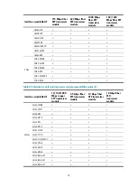
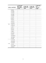
Table 73
Crossover cable pinouts
Pinout No.
A
B
1 Orange/white
Green/white
2 Orange
Green
3 Green/white
Orange/white
4 Blue Blue
5 Blue/white
Blue/white
6 Green
Orange
7 Brown/white
Brown/white
8 Brown
Brown
NOTE:
Strictly follow the pinouts in the above tables when identifying or making the two types of Ethernet cables;
otherwise, the communication quality might be affected.
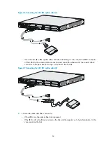
Connecting an Ethernet cable
1.
Connect one end of an Ethernet cable to an Ethernet port on the module and the other end to the
Ethernet port on the peer device. Because the Ethernet port of the module supports MDI/MDIX
auto-sensing, you can use a straight-through cable or crossover cable to connect the port.
2.
Examine the status of the LED of the Ethernet port after power-on. For the status of the LED, see the
relevant part in this manual.
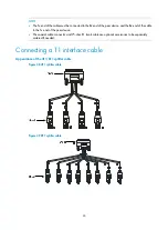
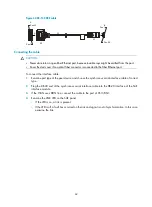
Connecting an optical interface cable
Appearance of transceiver module, optical fiber and connector
Optical interfaces need to work with SFP, SFP+, XFP, or QSFP+ transceiver modules and optical fibers
with LC-type connectors.
Figure 39
SFP transceiver module


