38
NOTE:
•
T3 represents the tertiary group rate of the T series in the TDM system, which is 44.736 Mbps.
•
A T3 channel can be channelized into 28 T1 channels through the demultiplex processes of T23 and
T12, with each T1 channel supporting both the T1 and CT1 operating modes. T23 indicates either
T2-to-T3 multiplex or T3-to-T2 demultiplex, and T12 indicates T1-to-T2 multiplex or T2-to-T1 demultiplex.
T23 and T12 discussed here represent the demultiplex process.
Front panel
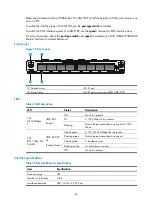
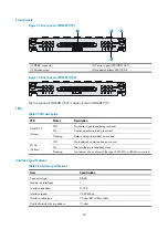
Figure 28
Front panel
(1) Carrier signal LED (LINK/ACT)
(2) TX interface
(3) RX interface
(4) Captive screw
(5) Loopback/alarm LED (LP/AL)
LEDs
Table 41
LED description
LED Status
Description
LINK/ACT
Off
No carrier signals are being received.
On
Carrier signals are being received.
Flashing
Data is being transmitted or received.
LP/AL
Off
No loopback or alarms occur.
On
The interface is in loopback state.
Flashing
A minimum of one alarm of the type of AIS, LFA, or RAI has occurred.
•
LFA
—Loss of frame alignment.
•
AIS
—Alarm indication signal.
•
RAI
—Remote alarm indication.
Interface specifications
Table 42
Interface specifications
Item Specification
Connector type
SMB
Number of interfaces
2

