background image


15 


No fan tray is provided with the firewall. Purchase fan trays as required. The firewall supports the 
FAN-20B-2-A and FAN-20F-2-A fan trays that are hot swappable. 

The installation procedures  for  the  FAN-20B-2-A and  the  FAN-20F-2-A  fan trays are  similar.  The 
following procedure installs a FAN-20B-2-A fan tray. 

To install a fan tray: 

1. 

Wear an ESD wrist strap and make sure it makes good skin contact and is reliably grounded. 

2. 

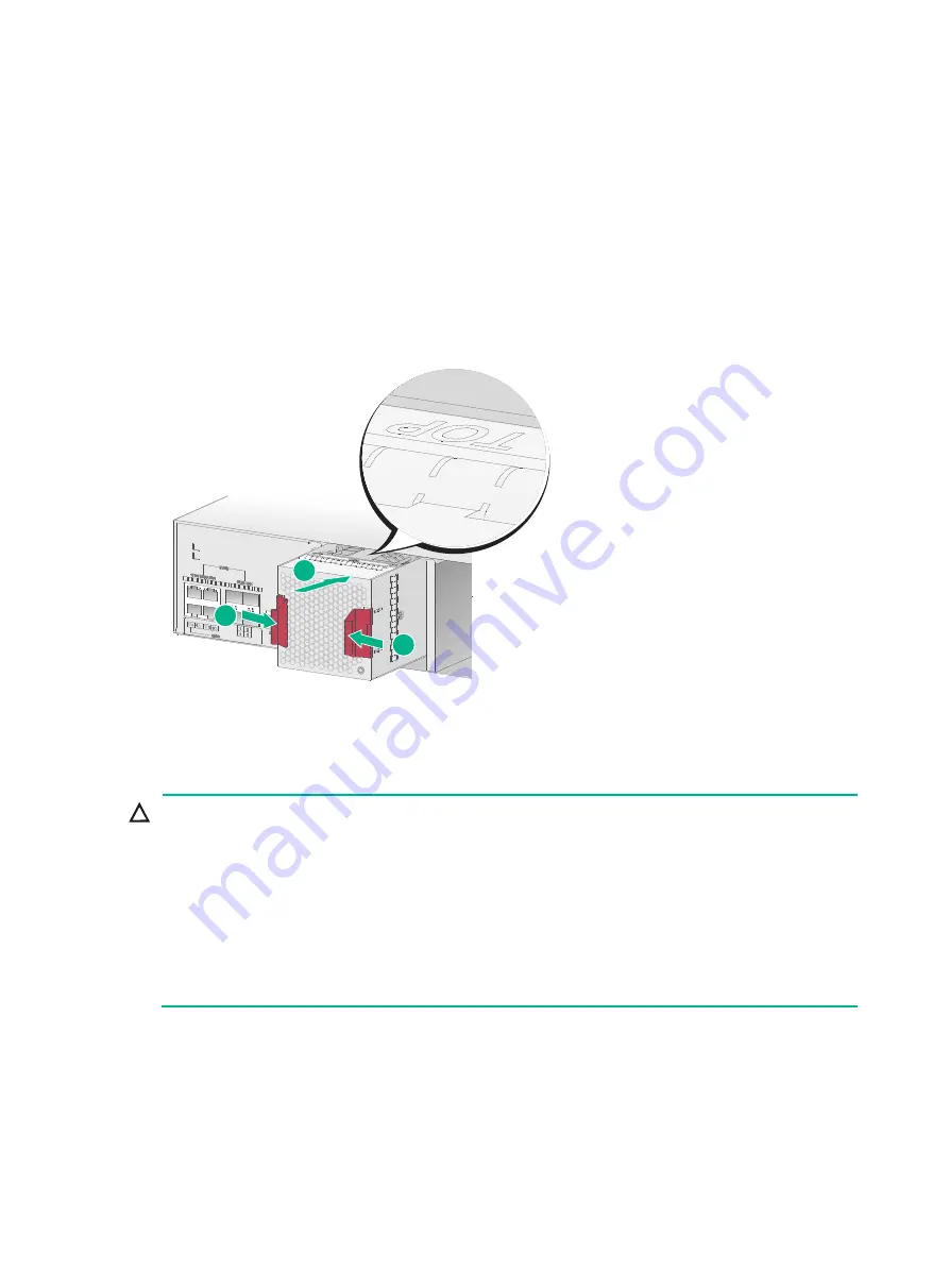
Orient the fan tray with the "TOP" mark on the top, grasp the fan tray handle with one hand, and 
support its bottom with the other hand. Slide the fan tray along the guide rails into the slot until it 
has a firm contact with the backplane. 

Figure2-8 Installing a fan tray 


Installing an MPU or an interface module 


CAUTION: 

  Only slots 0/0 and 1/0 on the F5030-D/F5060-D/F5080-D support installation of MPUs. 

  If the F5030-D/F5060-D/F5080-D is installed with two MPUs, you can hot swap an MPU. If the 

F5030-D/F5060-D/F5080-D is installed with only one MPU, you cannot hot swap the MPU. 

  Interface modules are not hot swappable. 

  To avoid module damage, do not touch the surface-mounted components on an interface module 

directly with your hands. 

  Install a filler panel over empty MPU and interface module slots to prevent dust and ensure good 

ventilation in the chassis. 


No MPU or interface module is provided with the firewall. Purchase  them  as required. The 
installation procedure is the same for MPUs and interface modules. 

To install an interface module: 

1. 

Wear an ESD wrist strap and make sure it makes good skin contact and is reliably grounded. 

2. 

Remove the screws on the filler panel with a Phillips screwdriver and remove the filler panel. 

Keep the filler panel for future use. 

1

2

1

Summary of Contents for SecPath F5000-A

Page 1: ...g a fiber port 17 Connecting the power cord 19 Connecting an AC power cord 19 Connecting a DC power cord 20 Verifying the installation 21 3 Accessing the firewall for the first time 3 22 Setting up the configuration environment 3 22 Powering on the firewall 3 22 Checking before power on 3 22 Powering on the firewall 3 22 Checking after power on 3 22 Logging in to the firewall 3 24 Logging in from ...

Page 2: ... Chassis and FRU views and technical specifications 7 38 Chassis views 7 38 F5030 F5060 F5080 F5000 M F5030 6GW F5000 A 7 38 F5030 D F5060 D F5080 D 7 39 Slots 7 40 FRU views 7 40 MPUs 7 40 Interface modules 7 40 Power modules 7 43 Fan trays 7 44 Technical specifications 7 45 Dimensions and weights 7 45 Memory and storage media 7 46 Power consumption 7 46 Power module specifications 7 46 Fan tray ...

Page 3: ...recommendations Do not place the firewall on an unstable case or desk The firewall might be severely damaged in case of a fall Make sure the ground is dry and flat and anti slip measures are in place Keep the chassis and installation tools away from walk areas Keep the chassis clean and dust free Do not place the firewall near water or in a damp environment Prevent water or moisture from entering ...

Page 4: ...ted transceiver modules to avoid damage caused by built up dust Insert a dust plug into empty fiber ports Handling safety When you move the firewall follow these guidelines Move and unpack the firewall carefully to avoid firewall damage Unpack the firewall at least half an hour and power on the firewall at least two hours after you move it from a place below 0 C 32 F to the equipment room This pre...

Page 5: ...ifespan of the firewall For the temperature and humidity requirements of the firewall see Table1 2 Table1 2 Temperature humidity requirements Temperature Relative humidity Operating Without hard disks 0 C to 45 C 32 F to 113 F With hard disks 5 C to 40 C 41 F to 104 F Storage 40 C to 70 C 40 F to 158 F Operating Without hard disks 5 RH to 95 RH noncondensing With hard disks 10 RH to 90 RH nonconde...

Page 6: ...erent fan trays Rear to front airflow The FAN 20F 2 A fan tray blows air from the power module side to the port side as shown in Figure1 1 The fan tray has a blue fan tray handle Front to rear airflow The FAN 20B 2 A fan tray draws air from the port side to the power module side as shown in Figure1 2 The fan tray has a red fan tray handle Figure1 1 Rear to front airflow provided by the FAN 20F 2 A...

Page 7: ... strap tight around your wrist to keep good contact with the skin 3 Secure the wrist strap lock and the alligator clip lock together 4 Attach the alligator clip to the rack Figure1 3 Attaching an ESD wrist strap 1 ESD wrist strap 2 Lock 3 Alligator clip EMI All electromagnetic interference EMI sources from outside or inside of the firewall and application system adversely affect the firewall in th...

Page 8: ...the device If a network cable is routed from outdoors for connecting to an Ethernet port on the firewall connect the network cable first to a network port lightning arrester before connecting it to the port IMPORTANT No network port lightning arrester or AC power lightning arrester is provided with the device Prepare them as required For the technical specifications and installation instructions f...

Page 9: ...ing Without hard disks 5 RH to 95 RH noncondensing With hard disks 10 RH to 80 RH noncondensing Storage 5 RH to 95 RH noncondensing Cleanness Dust concentration 3 104 particles m3 No dust on desk within three days ESD prevention The firewall and the rack are reliably grounded The equipment room is dust proof The humidity and temperature are at an acceptable level Always wear ESD clothing ESD glove...

Page 10: ...f the AC power receptacle is reliably grounded Optional A power lightning arrester is installed Power supply Verify that the power system at the installation site meets the requirements of the power modules including the input method and rated input voltage Tools and accessories Installation accessories supplied with the firewall User supplied tools Reference Documents shipped with the firewall On...

Page 11: ...d if you want to open the chassis contact the local agent of H3C for permission Otherwise H3C shall not be liable for any consequence caused thereby The installation method is similar for the F5030 F5060 F5080 F5030 D F5060 D F5080 D F5000 M F5030 6GW and F5000 A firewalls This section uses the F5080 as an example ...

Page 12: ...alling or using the firewall connect the grounding cable to it correctly Do not connect the firewall grounding cable to a fire main or lightning rod Ground the firewall Install fan trays Install MPUs or interface modules Install power modules End Install the firewall in a 19 inch rack Start Connect power cords Verify the installation Install hard disks Connect Ethernet interface cables ...

Page 13: ... Connect the other end of the grounding cable to the grounding strip on the rack Figure2 2 Grounding the firewall by using the primary grounding point Installing the firewall in a standard 19 inch rack WARNING To avoid bodily injury and device damage at least two persons are required to install the firewall CAUTION Ensure a clearance of 1 RU 44 45 mm or 1 75 in between the firewall and walls or ot...

Page 14: ...positions on the front and rear rack posts respectively Four cage nuts are required on each front rack post and two are required on each rear rack post 4 Install cages nuts at the marked positions 5 Use M6 screws to attach two slide rails to the rear rack posts Figure2 3 Installing cage nuts and slide rails 6 Use the provided M4 screws to attach the mounting brackets and chassis rails to both side...

Page 15: ...rack posts 8 Fasten the M6 rack screws with a Phillips screwdriver to secure the mounting brackets to the front rack posts Figure2 5 Mounting the firewall to the rack Installing a power module CAUTION Make sure the power module is powered off and the device is correctly grounded before installation Install a filler panel over an empty power module slot to prevent dust and ensure good ventilation i...

Page 16: ...ower module along the guide rails into the slot until it has firm contact with the slot Figure2 7 Installing an AC power module Installing a fan tray CAUTION Before installation make sure the airflow direction provided by the fan tray meets the requirements for installation ventilation The device comes with both fan tray slots empty To ensure good ventilation you must install two fan trays of the ...

Page 17: ...y slots 0 0 and 1 0 on the F5030 D F5060 D F5080 D support installation of MPUs If the F5030 D F5060 D F5080 D is installed with two MPUs you can hot swap an MPU If the F5030 D F5060 D F5080 D is installed with only one MPU you cannot hot swap the MPU Interface modules are not hot swappable To avoid module damage do not touch the surface mounted components on an interface module directly with your...

Page 18: ...stall a filler panel over empty hard disk slots to avoid damage caused by build up dust Before using a hard disk execute the fdisk and format commands from the CLI to partition and format the hard disk The device does not come with any hard disks and cannot recognize hard disks from other vendors Purchase hard disks from H3C as needed To install a hard disk 1 Wear an ESD wrist strap and make sure ...

Page 19: ...cted optical fibers or transceiver modules might emit invisible laser light Do not stare into beams or view directly with optical instruments when the switch is operating CAUTION Never bend or curve a fiber excessively The bend radius of a fiber must be not less than 100 mm 3 94 in Keep the fiber end clean Make sure the fiber connector matches the transceiver module Before connecting a fiber make ...

Page 20: ...all a transceiver module Pull the bail latch on the transceiver module upwards to catch the knob on the top of the transceiver module Take the transceiver module by its two sides and push the end without the bail latch gently into the port until it snaps into place 3 Remove the dust cap from the optical fiber connector and use dust free paper and absolute alcohol to clean the end face of the fiber...

Page 21: ...nd the power source is powered off before connecting the power cord Connecting an AC power cord 1 Connect one end of the AC power cord to the AC input power receptacle on the power module 2 Use a removable cable tie to secure the AC power cord to the power module handle 3 Connect the other end of the power cord to the AC power source 1 2 3 4 ...

Page 22: ...ectly orient the DC power cord plug with the power receptacle on the power module and insert the plug into the receptacle 2 Use a removable cable tie to secure the DC power cord to the power module handle 3 Connect the other end of the power cord to the DC power source 1 2 4 3 ...

Page 23: ...installation After installation verify that There is enough space for heat dissipation around the firewall and the firewall is steady All screws are fastened The grounding cable and power cord are securely connected The correct power source is used 1 2 4 3 ...

Page 24: ...ted The correct power source is used The console cable is correctly connected the terminal or PC used for configuration has started and the configuration parameters have been correctly set The interface module if any is correctly installed Powering on the firewall Switch on the power source of the firewall Checking after power on After powering on the firewall verify that The LEDs on the front pan...

Page 25: ...assed Known answer test for SHA256 passed Known answer test for SHA384 passed Known answer test for SHA512 passed Known answer test for HMAC SHA1 passed Known answer test for HMAC SHA224 passed Known answer test for HMAC SHA256 passed Known answer test for HMAC SHA384 passed Known answer test for HMAC SHA512 passed Known answer test for AES passed Known answer test for RSA signature verification p...

Page 26: ...rl B at the prompt the system starts to read and decompress program files To enter the EXTENDED BOOT menu afterwards you need to reboot the device Logging in to the firewall For more information about logging in to the device see the configuration guides and command references for the device Logging in from the console port You can use the console port to access the firewall for the first time The...

Page 27: ...C to the Ethernet management interface on the firewall 2 Configure an IP address in subnet 192 168 0 0 24 for the PC Make sure the PC and the firewall are reachable to each other The PC must use a different IP address than the Ethernet management interface 3 Start a browser enter 192 168 0 1 in the address bar and press Enter 4 Enter the default username admin and password admin and then click Log...

Page 28: ...rotating axis even if they are not rotating To replace a fan tray 1 Holding the fan tray handle with one hand and supporting the fan tray bottom with the other pull the fan tray out of the slot along the guide rails 2 Put the removed fan tray into an antistatic bag 3 Install a new fan tray For the installation procedure see Installing a fan tray Figure4 1 Removing a fan tray Replacing a power modu...

Page 29: ...Install a new power module For the installation procedure see Installing a fan tray Figure4 3 Removing the DC power module Replacing an MPU or an interface module CAUTION You can hot swap an MPU only when the F5030 D F5060 D F5080 D has two MPUs Interface modules are not hot swappable The replacement procedure is the same for MPUs and interface modules To replace an interface module 1 Power off th...

Page 30: ...e execute the umount command from the CLI to unmount all the file systems before removing a hard disk Hard disks are not hot swappable To replace a hard disk 1 Wear an ESD wrist strap and make sure it makes good skin contact and is reliably grounded 2 Press the red button on the hard disk panel to release the locking lever 3 Hold the locking lever and pull the hard disk out of the slot 4 Install a...

Page 31: ...en plating To replace a transceiver module 1 Use the shutdown command in interface view at the CLI to shut down the optical source before you remove the fiber connector 2 Remove the LC connectors with the optical fiber from the transceiver module and install dust caps to the LC connectors 3 Pivot the clasp of the transceiver module down to the horizontal position and gently pull the transceiver mo...

Page 32: ... CPU Ver 1 0 CPLD_A 1 0 CPLD_B 1 0 CFCard Num 0 Displaying the software and hardware version information for the firewall Use the display version command to display software and hardware version information for the firewall Sysname display version H3C Comware Software Version 7 1 064 Alpha 9606P03 Copyright c 2004 2017 New H3C Technologies Co Ltd All rights reserved H3C SecPath F5060 uptime is 0 w...

Page 33: ...ame display device manuinfo Slot 1 CPU 0 DEVICE_NAME SecPath F5060 DEVICE_SERIAL_NUMBER 210235A1XYH175000008 MAC_ADDRESS 1CAB 3497 D7DE MANUFACTURING_DATE 2017 06 13 VENDOR_NAME H3C Fan 0 The operation is not supported on the specified fan Fan 1 The operation is not supported on the specified fan Fan 2 The operation is not supported on the specified fan Fan 3 The operation is not supported on the ...

Page 34: ... average CPU usage at intervals of 5 minutes Displaying the memory usage of the firewall Use the display memory command to display the memory information of the firewall Sysname display memory Memory statistics are measured in KB Slot 1 Total Used Free Shared Buffers Cached FreeRatio Mem 32870736 4244812 28625924 0 2048 200756 87 1 Buffers Cache 4042008 28828728 Swap 0 0 0 Table5 3 Output descript...

Page 35: ...ormal Slot 1 Power 1 Status Absent Table5 4 Output description Field Description Power Number of the power module Status Power module state Normal The power module is operating correctly Absent The power module is not in position Abnormal The power module has failed Displaying the temperature information of the firewall Use the display environment command to display the temperature information of ...

Page 36: ...es Typically you need to run display commands one by one To collect more information one time you can execute the display diagnostic information command in any view to display or save the operational statistics of multiple functional modules of the firewall Save the operational statistics of each functional module of the firewall Sysname display diagnostic information Save or display diagnostic in...

Page 37: ...interface number Available for all transceiver modules Rebooting the firewall CAUTION If the main system software image file does not exist do not use the reboot command to reboot the firewall Specify the main system software image file first and then reboot the firewall The precision of the rebooting timer is 1 minute 1 minute before the rebooting time the firewall prompts REBOOT IN ONE MINUTE an...

Page 38: ...power cords of the firewall are firmly connected 4 Verify that the power cords are not damaged 5 If the issue persists contact your local sales agent Configuration terminal display problem Symptom The configuration terminal displays nothing or garbled text when the firewall is powered on Solution To solve the issue 1 Verify that the power supply system is operating correctly 2 Verify that the cons...

Page 39: ...firewall keeps rising If the temperature has reached the alarming level high temperature alarm threshold back up data immediately power off the firewall and contact your local sales agent Information about the firewall temperature in the display environment command output varies by firewall model 4 If the issue persists contact your local sales agent Software loading failure Symptom Software loadi...

Page 40: ...ront panel 1 Interface module slots slots 1 through 8 2 Hard disk slot HD0 3 Hard disk slot HD1 4 LEDs Rear panel On the rear panel the F5030 F5060 F5080 F5000 M F5030 6GW F5000 A firewall provides four combo interfaces including one management Ethernet port two USB ports one console port two fan tray slots and two power module slots Figure7 2 Rear panel 1 10 100 1000BASE T copper Ethernet port co...

Page 41: ... 1 0 3 Hard disk slot HD0 4 Hard disk slot HD1 5 LEDs Rear panel On the rear panel the F5030 D F5060 D F5080 D firewall provides the following ports and slots Four combo interfaces including four 10 100 1000BASE T auto sensing copper Ethernet ports and four 1000BASE X fiber Ethernet ports Two USB ports One console port Two fan tray slots Two power module slots Figure7 4 Rear panel 1 10 100 1000BAS...

Page 42: ... one 100 1000BASE TX management Ethernet port Only slots 0 0 and 1 0 on the F5030 D F5060 D F5080 D firewall support the NSQM1MPULA MPU Figure7 5 Front view 1 USB port host mode Type A connector 2 Console port CONSOLE 3 Management Ethernet port MANAGEMENT 4 LEDs 5 Captive screw 6 Ejector lever Interface modules CAUTION The interface modules are not hot swappable The 10GE fiber ports on an NSQM1G4X...

Page 43: ...SQM1TG8A The NSQM1TG8A interface module provides eight 10GBASE R fiber Ethernet ports Figure7 6 NSQM1TG8A front view 1 LED 2 10GBASE R fiber Ethernet ports 3 Captive screw 4 Ejector lever NSQM1QG2A The NSQM1QG2A interface module provides two 40GBASE R fiber Ethernet ports Figure7 7 NSQM1QG2A front view 1 LED 2 40GBASE R fiber Ethernet ports 3 Captive screw 4 Ejector lever NSQM1G4XS4 The NSQM1G4XS4...

Page 44: ...T8A front view 1 LED 2 10 100 1000BASE T copper Ethernet ports 3 Captive screw 4 Ejector lever NSQM1GP8A The NSQM1GP8A interface module provides eight 1000BASE X fiber Ethernet ports Figure7 10 NSQM1GP8A front view 1 LED 2 1000BASE X fiber Ethernet ports 3 Captive screw 4 Ejector lever NSQM1GT4PFCA The NSQM1GT4PFCA interface module provides four 10 100 1000BASE T copper Ethernet ports that support...

Page 45: ...l and power module slot PWR1 empty You can install two power modules to achieve 1 1 power redundancy or install only one power module If two power modules are installed you can hot swap a power module If only one power module is installed power off the firewall before you remove the power module AC power module Figure7 12 AC power module front view 1 Retaining latch 2 Handle 3 Power receptacle 2 3...

Page 46: ...B 2 A fan trays are available for the firewall The FAN 20F 2 A fan tray provides power module side intake and port side exhaust airflow The FAN 20B 2 A fan tray provides port side intake and power module side exhaust airflow For the fan tray specifications see Fan tray specifications To ensure adequate heat dissipation the firewall must have two fan trays of the same model installed when it is ope...

Page 47: ...sis 88 1 440 660 mm 3 47 17 32 25 98 in excluding rubber feet and mounting brackets 20 1 kg 44 31 lb MPU NSQM1MPULA 19 8 189 212 4 mm 0 78 7 44 8 36 in 0 6 kg 1 32 lb Interface module NSQM1TG8A 19 8 189 212 4 mm 0 78 7 44 8 36 in 0 55 kg 1 21 lb NSQM1QG2A 19 8 189 212 4 mm 0 78 7 44 8 36 in 0 55 kg 1 21 lb NSQM1G4XS4 19 8 189 212 4 mm 0 78 7 44 8 36 in 0 54 kg 1 19 lb NSQM1GT8A 19 8 189 212 4 mm 0...

Page 48: ...er consumption of the MPUs and interface modules as shown in Table7 5 Table7 5 Power consumption Item Specification Firewall chassis F5030 F5060 F5080 F5000 M F5030 6GW 191 W F5000 A 199 W F5030 D F5060 D F5080 D 250 W MPU NSQM1MPULA 7 50 W Interface module NSQM1TG8A 12 96 W NSQM1QG2A 6 40 W NSQM1G4XS4 6 46 W NSQM1GT8A 3 03 W NSQM1GP8A 8 15 W NSQM1GT4PFCA 5 78 W Power module specifications Table7 ...

Page 49: ...e to the port side FAN 20B 2 A From the port side to the power module side Hot swapping Supported Max airflow volume 120 CFM Max power consumption 57 W Operating voltage 12 VDC Hard disk specifications Table7 9 NS SSD 480G SATA SFF specifications Item Specification Dimensions H W D 19 75 7 118 4 mm 0 75 2 98 4 66 in Weight 0 069 kg 0 15 lb Hot swapping Not supported Capacity 480 GB Operating tempe...

Page 50: ...compliance 802 3 802 3u and 802 3ab Interface type MDI MDI X autosensing Cable type Category 5 or higher twisted pair cable Transmission distance 100 m 328 08 ft Interface speed and duplex mode 10 Mbps half full duplex 100 Mbps half full duplex 1000 Mbps full duplex NOTE The media dependent interface MDI standard is typically used on the Ethernet port of network adapters The media dependent interf...

Page 51: ...SFP GE LH40 SM1550 1550 SMF 9 125 N A SFP GE LH80 SM1550 1550 SMF 9 125 N A SFP GE LH100 SM1550 1550 SMF 9 125 N A Table7 14 1000BASE X SFP transceiver module specifications 2 Transceiver module Transmission distance Transmitted optical power dBm Received optical power dBm SFP GE SX MM850 A 550 m 1804 46 ft 9 5 to 0 17 to 3 500 m 1640 42 ft 275 m 902 23 ft 220 m 721 78 ft 220 m 721 78 ft SFP GE LX...

Page 52: ...Table7 15 10 GE fiber port specifications Item Specification Connector type LC Transceiver module type SFP Standard compliance 10GBASE R Interface speed LAN PHY 10 Gbps Table7 16 SFP transceiver module specifications 1 Transceiver module Central wavelength nm Fiber mode Fiber diameter µm Mode bandwidth MHz km SFP XG SX MM850 A 850 MMF 50 125 2000 500 400 62 5 125 200 160 160 SFP XG LX220 MM1310 13...

Page 53: ...7 3 to 1 9 9 to 0 5 82 m 269 03 ft 66 m 216 54 ft 33 m 108 27 ft 26 m 85 30 ft 8 m 26 25 ft SFP XG LX220 MM131 0 220 m 721 78 ft 10 31 Gbps 6 5 to 0 5 6 5 to 1 5 220 m 721 78 ft 100 m 328 08 ft 220 m 721 78 ft 220 m 721 78 ft SFP XG LX SM1310 10 km 6 21 miles 10 31 Gbps 8 2 to 0 5 14 4 to 0 5 SFP XG LH40 SM1550 40 km 24 85 miles 10 31 Gbps 4 7 to 4 15 8 to 1 40 GE fiber port Table7 18 40 GE fiber ...

Page 54: ...ion speed Transmitted optical power dBm Received optical power dBm QSFP 40G SR4 MM850 100 m 328 08 ft 40 Gbps 7 6 to 0 9 5 to 2 4 150 m 492 13 ft QSFP 40G LR4 WDM1300 10 km 6 21 miles 40 Gbps 7 to 2 3 13 7 to 2 3 QSFP 40G CSR4 MM850 300 m 984 25 ft 40 Gbps 7 6 to 0 9 9 to 2 4 400 m 1312 34 ft 8 Appendix B LEDs Front panel and rear panel LEDs Table8 1 Front panel and rear panel LED description LED ...

Page 55: ...dy green A link is present Off No link is present Ethernet fiber port LED combo interface 1000BASE X Flashing green The port is receiving or sending data at 1000 Mbps Steady green A 1000 Mbps link is present Off No link is present MPU LEDs Table8 2 MPU LED description LED Mark Status Description System LED SYS Flashing green 0 5 Hz The system is operating correctly Flashing green 4 Hz The system i...

Page 56: ...ving or sending data at 1000 Mbps Steady green A 1000 Mbps link is present Off No link is present 10GBASE R Flashing green The port is receiving or sending data at 10 Gbps Steady green A 10 Gbps link is present Off No link is present 40GBASE R Flashing green The port is receiving or sending data at 40 Gbps Steady green A 40 Gbps link is present Off No link is present 9 Appendix C Cables Console ca...

Page 57: ... two twisted pair cable segments with a repeater At most four repeaters can be added which means five segments can be joined together to provide a transmission distance of 500 m 1640 42 ft Ethernet twisted pair cables can be classified into category 3 category 4 category 5 category 5e category 6 and category 7 cables based on performance In LANs category 5 category 5e and category 6 are commonly u...

Page 58: ...tion EIA TIA cabling specifications define two standards 568A and 568B for cable pinouts Standard 568A pin 1 white green stripe pin 2 green solid pin 3 white orange stripe pin 4 blue solid pin 5 white blue stripe pin 6 orange solid pin 7 white brown stripe pin 8 brown solid Standard 568B pin 1 white orange stripe pin 2 orange solid pin 3 white green stripe pin 4 blue solid pin 5 white blue stripe ...

Page 59: ... Pin 10Base T 100Base TX 1000Base T Signal Function Signal Function 1 Tx Sends data BIDA Bi directional data cable A Straight through cable white orange orange white green blue white blue green white brown brown 1 2 3 4 5 6 7 8 white orange orange white green blue white blue green white brown brown 1 2 3 4 5 6 7 8 Crossover cable white orange orange white green green white orange orange white gree...

Page 60: ... data cable C To ensure normal communication the pins for sending data on one port must correspond to the pins for receiving data on the peer port When both ports on the two devices are MDI or MDIX use a crossover Ethernet cable when one port is MDI and the other is MDIX use a straight through Ethernet cable To summarize straight through and crossover cables connect the following devices Straight ...

Page 61: ...ht source and transmission distance Uses lasers as the light source often within campus backbones for distance of several thousand meters Uses LEDs as the light source often within LANs or distances of a couple hundred meters within a campus network Table9 6 Allowed maximum tensile force and crush load Period of force Tensile load N Crush load N mm Short period 150 500 Long term 80 100 Fiber conne...

Page 62: ...cohol to clean the end face of the two fiber connectors You can brush the end faces only in one direction Never bend or curve a fiber If the fiber has to pass through a metallic board hole or bend along the acute side of mechanical parts the fiber must wear jackets or cushions ...

Reviews: