


Operation Manual – RPR
H3C S9500 Series Routing Switches
Chapter 1 RPR Configuration
1-11
To do...
Use the command...
Remarks
Configure the protection
reversion mode
rpr reversion-mode
{
revertive
|
non-revertive
}
Optional
Revertive mode applies
by default.
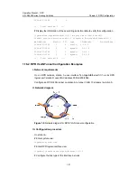
1.5 Configuring Ringlet Selection Table
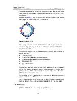
Each RPR station maintains a ringlet selection table, based on which the decision as to
which ringlet should be selected to transmit frames is made. A ringlet selection table
entry contains such information as the MAC address of a station, the ringlet through
which frames are transmitted.
The RPR ringlet selection table comprises a static ringlet selection table, a dynamic
ringlet selection table, a default ringlet selection table, an overall ringlet selection table,
an IPv6 ringlet selection table, and a VRRP ringlet selection table.
z
Static ringlet selection table is administratively configured to specify the ringlet for
delivering a frame to a destination station.
z
Dynamic ringlet selection table is built dynamically based on the topology
database.
z
Default ringlet selection table specifies the default ringlet for delivering frames.
z
Overall ringlet selection table is created from the above three tables. Static ringlet
selection table has the highest priority. If a static ringlet selection entry is available
for reaching a destination station, it is added into the overall ringlet selection table.
If no static entry is available, the system looks at the dynamic ringlet selection
table. If two shortest paths are available, default ringlet selection applies to pick up
one from them. The selected entry is then added into the overall ringlet selection
table. When sending frames, the station consults this table to identify the path to
the destination MAC address.
Note:
Each station on the RPR can be configured with only one VRRP group and it can only
be configured on the VLAN virtual interface to which the PVID corresponds.