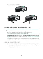
14
IMPORTANT:
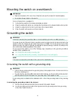
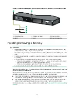
Orient the grounding cable as shown in
so you can easily install or remove the
expansion card.
Figure 15 Connecting the grounding cable to the chassis
(1) Grounding screw
(2) Ring terminal
(3) Grounding sign
(4) Grounding hole
(5) Grounding cable
Connecting the grounding cable to a grounding strip (for the S5560X-30C-PWR-EI and
S5560X-54C-PWR-EI switches)
1.
Remove the hex nut of a grounding post on the grounding strip.
2.
Cut the grounding cable to a length required for connecting to the grounding strip.
3.
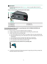
Attach a ring terminal to the grounding cable:
a.
Use a wire stripper to strip 5 mm (0.20 in) of insulation off the end of the grounding cable.
b.
Slide the heat-shrink tubing onto the cable and insert the bare metal part into the end of the
ring terminal.
c.
Use a crimper to secure the metal part of the cable to the ring terminal.
d.
Slide the heat-shrink tubing down the cable until the tube covers the joint.
e.
Use a heat gun to shrink the tubing around the cable.
Figure 16 Attaching a ring terminal to the grounding cable
4.
Connect the ring terminal of the grounding cable to the grounding post of the grounding strip,
and fasten it with the removed hex nut.


