background image


2-17 

Figure 2-17 Connecting the grounding cable to the grounding strip 


(1) Grounding post 

(2) Grounding strip 

(3) Grounding cable 

(4) Hex nut 


Grounding the switch with a grounding conductor buried in 
the earth ground 

If the installation site does not have any grounding strips, but earth ground is available, hammer a 0.5 
m (1.64 ft) or longer angle iron or steel tube into the earth ground to serve as a grounding conductor. 

The dimensions of the angle iron must be a minimum of 50 × 50 × 5 mm (1.97 × 1.97 × 0.20 in). The 
steel tube must be zinc-coated and its wall thickness must be a minimum of 3.5 mm (0.14 in). 

Weld the yellow-green grounding cable to the angel iron or steel tube and treat the joint for corrosion 
protection. 

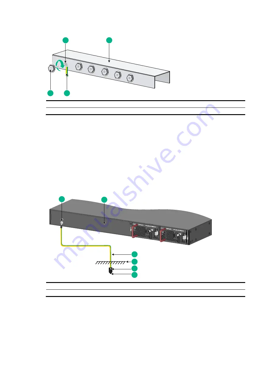
Figure 2-18 Grounding the switch by burying the grounding conductor into the earth ground 


(1) Grounding screw 

(2) Chassis rear panel 

(3) Grounding cable 

(4) Earth 

(5) Joint 

(6) Grounding conductor  


1

2

3

4

6

5

3

4

1

2

Summary of Contents for S5560S-EI Series

Page 1: ...H3C S5560S EI S5130S HI Switch Series Installation Guide New H3C Technologies Co Ltd http www h3c com Document version 6W107 20201116...

Page 2: ...espective owners Notice The information in this document is subject to change without notice All contents in this document including statements information and recommendations are believed to be accur...

Page 3: ...keywords that you enter literally as shown Italic Italic text represents arguments that you replace with actual values Square brackets enclose syntax choices keywords or arguments that are optional x...

Page 4: ...at contains additional or supplementary information TIP An alert that provides helpful information Network topology icons Convention Description Represents a generic network device such as a router sw...

Page 5: ...document might use devices that differ from your device in hardware model configuration or software version It is normal that the port numbers sample output screenshots and other information in the e...

Page 6: ...the power cord 2 22 Connecting the power cord for a PSR75 12A PSR150 A1 power supply 2 23 Connecting the power cord for a PSR150 D1 PSR560 56D power supply 2 24 Connecting the power cord for a PSR180...

Page 7: ...ii Fan tray failure 5 43 Configuration terminal display issues 5 43 No display 5 43 Garbled display 5 44...

Page 8: ...28S EI LS S5560S 28S EI GL S5560S 52S EI LS S5560S 52S EI LS S5560S 52S EI GL S5560S 28S PWR EI LS S5560S 28S PWR EI LS S5560S 28S PWR EI GL S5560S 52S PWR EI LS S5560S 52S PWR EI LS S5560S 52S PWR EI...

Page 9: ...ce is reserved at the air inlet and outlet vents for ventilation The rack or workbench has a good ventilation system Identify the hot aisle and cold aisle at the installation site and make sure ambien...

Page 10: ...uspension 75 m 0 4 mg m 3 Dust sedimentation 75 m to 150 m 15 mg m 2 h Sand 150 m 300 mg m 3 To maintain cleanliness in the equipment room follow these guidelines Keep the equipment room away from pol...

Page 11: ...or gasoline engines separately Do not place them in the same equipment room with the device Make sure the exhausted air of the engines will not flow into the equipment room or towards the air inlet of...

Page 12: ...tion tools No installation tools are provided with the switch Prepare installation tools yourself as required ESD wrist strap Flat blade screwdriver Phillips screwdriver Needle nose pliers Diagonal pl...

Page 13: ...ion Turn on the circuit breakers Operating correctly Turn off the circuit breakers Troubleshoot the switch No Yes End Connect interface cables Ground the switch Install fan trays Install power supplie...

Page 14: ...43 in orient the bracket with the wide flange inside the rack If the rack depth is in the range of 274 to 440 mm 10 79 to 17 32 in and the distance from the rear rack posts to the inner surface of the...

Page 15: ...S 28F EI S5560S 52F EI S5560S 28P EI S5560S 52P EI S5560S 28S EI S5560S 52S EI S5130S 28S HI S5130S 52S HI S5130S 28C HI S5130S 52C HI S5560S 28S PWR EI S5560S 52S PWR EI S5130S 28S PWR HI S5130S 28S...

Page 16: ...the front mounting brackets at the port side or the power supply side 2 Attach the front mounting brackets to the chassis a Align the round holes in the wide flange of one front mounting bracket with...

Page 17: ...been attached securely to the two sides of the switch 3 One person supports the chassis bottom with one hand holds the front part of the chassis with the other hand and pushes the chassis into the rac...

Page 18: ...unting brackets and shoulder screws to the switch 1 Align the round holes in the wide flange of one front mounting bracket with the screw holes in the port side mounting position on one side of the ch...

Page 19: ...nt the rear mounting brackets with the wide flange inside or outside the rack as required 4 Use M6 screws to attach the rear mounting brackets to the rear posts as shown in Figure 2 11 Do not fully ti...

Page 20: ...ge nuts to the rack posts 4 One person supports the chassis bottom with one hand holds the front part of the chassis with the other hand and pushes the chassis into the rack gently Make sure the shoul...

Page 21: ...inside the rack Figure 2 14 Mounting the switch in the rack with the wide flange of the rear mounting brackets outside the rack Mounting the switch on a workbench IMPORTANT Reserve a minimum of 10 cm...

Page 22: ...ze the potential for system damage maximize the safety at the site and minimize EMI susceptibility of the system You can ground the switch in one of the following ways depending on the grounding condi...

Page 23: ...a grounding strip 1 Cut the grounding cable to a length required for connecting to the grounding strip 2 Use a wire stripper to strip 20 mm 0 79 in of insulation off the end of the grounding cable The...

Page 24: ...e into the earth ground to serve as a grounding conductor The dimensions of the angle iron must be a minimum of 50 50 5 mm 1 97 1 97 0 20 in The steel tube must be zinc coated and its wall thickness m...

Page 25: ...ifications Installing a PSR75 12A PSR150 A1 PSR150 D1 power supply CAUTION To prevent damage to the power supply or the connectors on the backplane insert the power supply gently If you encounter a ha...

Page 26: ...upply in the chassis see callout 2 in Figure 2 22 If the captive screw cannot be tightly fastened verify the installation of the power supply Figure 2 22 Installing a PSR150 A1 power supply Removing a...

Page 27: ...he installation procedure is the same for the PSR180 56A PSR360 56A PSR560 56D PSR720 56A and PSR1110 56A power supplies The following procedure uses the PSR720 56A power supply as an example To insta...

Page 28: ...he following procedure uses the PSR720 56A power supply as an example To remove a PSR720 56A power supply 1 Wear an ESD wrist strap and make sure it makes good skin contact and is reliably grounded 2...

Page 29: ...lance Power supply model Available power source Connection procedure reference PSR75 12A AC power source Connecting the power cord for a PSR75 12A PSR150 A1 240V high voltage DC power source PSR150 A1...

Page 30: ...clip Insert the two ends of the clip into the holes in the brackets on the left of the power receptacle 3 Pull the power cord retainer clip leftwards see Figure 2 27 4 Connect the female connector of...

Page 31: ...connect the power cord always identify the polarity symbol on its wires The power cord connection procedure is the same for the PSR150 D1 and PSR560 56D power supplies The following procedure uses a P...

Page 32: ...it makes good skin contact and is reliably grounded 2 Plug the female connector end of the power cord into the input socket of the power supply see callout 1 in Figure 2 30 3 Use a cable tie to secur...

Page 33: ...e see expansion modules in Hardware Information and Specifications Installing an expansion module 1 Wear an ESD wrist strap and make sure it makes good skin contact and is reliably grounded 2 Use a Ph...

Page 34: ...d 2 Use a Phillips screwdriver to remove the screw that secures the expansion module 3 Open the ejector lever on the expansion module 4 Pull the expansion module slowly out of the slot along the guide...

Page 35: ...xample from the serial console port Figure 3 1 Connecting the switch to a configuration terminal As shown in Table 3 1 three types of console cables can be used for connecting the switch to a configur...

Page 36: ...th a crimped RJ 45 connector at one end for connecting to the serial console port of the switch and a DB 9 female connector at the other end for connecting to the serial port on a configuration termin...

Page 37: ...following installs the driver on the Windows system To install the driver on other operating systems see the installation guide in the driver compression package named by using the corresponding oper...

Page 38: ...er installation wizard 5 Click Finish after the drive installation is completed Figure 3 5 Finishing the driver installation 6 Connect the standard USB connector of the cable to the USB port of the co...

Page 39: ...PC by using a micro USB console cable 1 Connect the standard USB connector to the USB port of the PC 2 Connect the micro USB connector to the micro USB console port of the switch 3 Click the following...

Page 40: ...3 33 Figure 3 7 Device Driver Installation Wizard 6 Click Continue Anyway Figure 3 8 Software Installation 7 Click Finish...

Page 41: ...mation about the terminal emulator programs see the user guides for these programs Configure the terminal parameters as follows Bits per second 9 600 Data bits 8 Parity None Stop bits 1 Flow control N...

Page 42: ...ce and menu options differ with software versions For more information about Boot ROM menu options see the software matching release notes for the device After the startup completes you can access the...

Page 43: ...escription 1 Plan IRF fabric setup Plan the installation site and IRF fabric setup parameters Planning IRF fabric size and the installation site Identifying the master switch and planning IRF member I...

Page 44: ...he IRF member switches in different racks to implement the ToR access solution for a data center NOTE For the maximum IRF member devices supported by the switch see the release notes that come with th...

Page 45: ...he IRF physical ports can set up IRF connections only when operating at their highest speeds For example a 10 GE port must operate at 10 Gbps A GE port must operate at 1 Gbps Figure 4 2 and Figure 4 3...

Page 46: ...divided into two groups ports 1 to 24 port 51 and port 52 in one group and ports 25 to 50 in the other group To bind multiple ports to an IRF port make sure the ports are in the same group The ports i...

Page 47: ...and SFP transceiver modules and fibers to connect four switches Connecting the IRF member switches in one rack Use SFP cables to connect the IRF member switches in a rack as shown in Figure 4 4 The s...

Page 48: ...switches as planned Wear an ESD wrist strap when you connect IRF physical ports For how to connect SFP SFP cables or SFP SFP transceiver modules and fibers see H3C SFP SFP XFP SFP28 Transceiver Modul...

Page 49: ...multi active detection MAD mechanism to detect the presence of multiple identical IRF fabrics and handle collisions For more information about MAD detection see the IRF configuration guide or virtual...

Page 50: ...H3C PSR560 56D Power supply User Manual H3C PSR720 56A Power supply User Manual or H3C PSR1110 56A Power supply User Manual Solution To resolve the issue 1 Verify that the power cord is correctly conn...

Page 51: ...cable does not have any problems and the PC settings are correct 4 If the issue persists contact H3C Support Garbled display Symptom The display on the PC is garbled Solution To resolve the issue 1 V...

Page 52: ...WR HI 2 30 3 Removable components and compatibility matrixes 3 31 Removable components and their compatibility with the device 3 31 Power supplies 3 32 Expansion modules 3 33 4 Ports and LEDs 4 34 Por...

Page 53: ...5560S 52P EI LS S5560S 52P EI GL S5560S 28S EI LS S5560S 28S EI LS S5560S 28S EI GL S5560S 52S EI LS S5560S 52S EI LS S5560S 52S EI GL S5560S 28S PWR EI LS S5560S 28S PWR EI LS S5560S 28S PWR EI GL S5...

Page 54: ...1 1 1 1 10 100 1000 BASE T autosensing Ethernet port 24 The rightmost eight ports and their corresponding SFP ports form combo interfaces 48 24 The rightmost eight ports and their corresponding SFP po...

Page 55: ...s 32 W Maximum power consumption Single PSR75 12A input 29 W Single PSR150 A1 input 32 W Single PSR150 D1 input 35 W Dual PSR75 12A inputs 32 W Dual PSR150 A1 inputs 39 W Dual PSR150 D1 inputs 44 W Si...

Page 56: ...90 VAC to 290 VAC 47 to 63 Hz 180 VDC to 320 VDC PSR150 A1 Rated voltage 100 VAC to 240 VAC 50 or 60 Hz Max voltage 90 VAC to 264 VAC 47 to 63 Hz PSR150 D1 You can use a 48 VDC power source in the equ...

Page 57: ...onnect both ports USB port 1 1 Management Ethernet port 1 1 10 100 1000 BASE T autosensing Ethernet port 24 The rightmost four ports and their corresponding SFP ports form combo interfaces 48 SFP port...

Page 58: ...13 F Relative humidity 5 to 95 noncondensing Fire resistance compliance UL 62368 1 EN 62368 1 IEC 62368 1 UL 60950 1 EN 60950 1 IEC 60950 1 GB4943 1 Table1 5 PoE power capacity of the S5560S 28S PWR E...

Page 59: ...6 5 kg 14 33 lb 5 kg 11 02 lb 5 kg 11 02 lb Console port 1 Micro USB console port 1 serial console port Only the Micro USB console port is available when you connect both ports USB port 1 1 1 1 Manag...

Page 60: ...ce in the equipment room or an RPS H3C RPS800 A or RPS1600 A Minimum power consumption Single PSR75 12A input 15 W Single PSR150 A1 input 18 W Single PSR150 D1 input 18 W Dual PSR75 12A inputs 17 W Du...

Page 61: ...28C P WR HI S5130S 52C PWR HI Dimension s H W D 43 6 440 460 mm 1 72 17 32 18 11 in Weight 8 5 kg 18 74 lb 8 5 kg 18 74 lb 9 5 kg 20 94 lb 9 kg 19 84 lb 9 5 kg 20 94 lb Console port 1 Micro USB conso...

Page 62: ...ge range 115 VAC to 240 VAC 50 Hz or 60 Hz Max voltage range 102 5 VAC to 264 VAC 47 Hz to 63 Hz PSR560 56D Rated voltage range 48 VDC to 60 VDC Max voltage range 36 VDC to 72 VDC For PSR560 56D DC in...

Page 63: ...d 1 PSR560 56D 1210 W 90 W 2 PSR560 56D 1050 W 90 W 1 PSR720 56A and 1 PSR360 56A 1010 W 90 W 1 PSR1110 56A 1040 W 90 W 1 PSR560 56D and 1 PSR360 56A 850 W 90 W 1 PSR720 56A 650 W 90 W 2 PSR360 56A 65...

Page 64: ...480 W 30 W 1 PSR360 56A 280 W 30 W 280 W 30 W 2 PSR180 56A 185 W 30 W 185 W 30 W 1 PSR180 56A 90 W 30 W 90 W 30 W Table1 10 PoE power capacity of the S5130S 28C PWR HI and S5130S 52C PWR HI switches P...

Page 65: ...acity Max PoE power capacity per port PSR360 56A 1 PSR1110 56A 810 W 30 W 900 W 30 W 1 PSR560 56D and 1 PSR360 56A 810 W 30 W 810 W 30 W 1 PSR720 56A 600 W 30 W 600 W 30 W 2 PSR360 56A 600 W 30 W 600...

Page 66: ...LED PWR2 10 Power supply 1 status LED PWR1 11 SFP port LED 12 Management Ethernet port LED ACT LINK 13 SFP port Figure2 2 Rear panel 1 Grounding screw 2 Power supply 1 PWR1 3 Power supply 2 PWR2 The S...

Page 67: ...s LED PWR2 9 Power supply 1 status LED PWR1 10 SFP port 11 SFP port LED Figure2 4 Rear panel 1 Grounding screw 2 Power supply 1 PWR1 3 Power supply 2 PWR2 The S5560S 52F EI switch comes with power sup...

Page 68: ...11 Power supply 2 status LED PWR2 12 Power supply 1 status LED PWR1 13 Management Ethernet port LED ACT LINK 14 SFP port LED Figure2 6 Rear panel 1 Grounding screw 2 Power supply 1 3 Power supply 2 Th...

Page 69: ...11 Power supply 2 status LED PWR2 12 Power supply 1 status LED PWR1 13 Management Ethernet port LED ACT LINK 14 SFP port LED Figure2 8 Rear panel 1 Grounding screw 2 Power supply 1 3 Power supply 2 Th...

Page 70: ...status LED PWR2 12 Power supply 1 status LED PWR1 13 Management Ethernet port LED ACT LINK 14 SFP port LED 15 SFP port LED 16 SFP port Figure2 10 Rear panel 1 Grounding screw 2 Power supply 1 3 Power...

Page 71: ...11 Power supply 2 status LED PWR2 12 Power supply 1 status LED PWR1 13 Management Ethernet port LED ACT LINK 14 SFP port LED Figure2 12 Rear panel 1 Grounding screw 2 Power supply 1 3 Power supply 2 T...

Page 72: ...SFP port 13 Power supply 2 status LED PWR2 14 Power supply 1 status LED PWR1 15 Management Ethernet port LED ACT LINK 16 SFP port LED Figure2 14 Rear panel 1 Grounding screw 2 Power supply 1 3 Power...

Page 73: ...1 Power supply 2 status LED PWR2 12 Power supply 1 status LED PWR1 13 Management Ethernet port LED ACT LINK 14 SFP port LED Figure2 16 Rear panel 1 Grounding screw 2 Power supply 1 3 Power supply 2 Th...

Page 74: ...17 SFP port Figure2 18 Rear panel 1 Grounding screw 2 Expansion module 3 Power supply 1 PWR1 4 Power supply 2 PWR2 The S5130S 28C HI switch comes with power supply slot 1 empty and power supply slot...

Page 75: ...status LED PWR2 12 Power supply 1 status LED PWR1 13 Management Ethernet port LED ACT LINK 14 SFP port LED 15 SFP port LED 16 SFP port Figure2 20 Rear panel 1 Grounding screw 2 Power supply 1 3 Power...

Page 76: ...FP port LED Figure2 22 Rear panel 1 Grounding screw 2 Expansion module 3 Power supply 1 PWR1 4 Power supply 2 PWR2 The S5130S 52C HI switch comes with power supply slot 1 empty and power supply slot 2...

Page 77: ...11 Power supply 2 status LED PWR2 12 Power supply 1 status LED PWR1 13 Management Ethernet port LED ACT LINK 14 SFP port LED Figure2 24 Rear panel 1 Grounding screw 2 Power supply 1 3 Power supply 2 T...

Page 78: ...SFP port 13 Power supply 2 status LED PWR2 14 Power supply 1 status LED PWR1 15 Management Ethernet port LED ACT LINK 16 SFP port LED Figure2 26 Rear panel 1 Grounding screw 2 Power supply 1 3 Power...

Page 79: ...rt 10 System status LED SYS 11 Power supply 2 status LED PWR2 12 Power supply 1 status LED PWR1 13 SFP port 14 SFP port LED Figure2 28 Rear panel 1 Grounding screw 2 Power supply 1 3 Power supply 2 Th...

Page 80: ...1 Power supply 2 status LED PWR2 12 Power supply 1 status LED PWR1 13 Management Ethernet port LED ACT LINK 14 SFP port LED Figure2 30 Rear panel 1 Grounding screw 2 Power supply 1 3 Power supply 2 Th...

Page 81: ...port LED Figure2 32 Rear panel 1 Grounding screw 2 Expansion module 3 Power supply 1 PWR1 4 Power supply 2 PWR2 The S5130S 28C PWR HI switch comes with power supply slot 1 empty and power supply slot...

Page 82: ...port LED Figure2 34 Rear panel 1 Grounding screw 2 Expansion module 3 Power supply 1 PWR1 4 Power supply 2 PWR2 The S5130S 52C PWR HI switch comes with power supply slot 1 empty and power supply slot...

Page 83: ...eries Removabl e componen ts S5130S 28S HI S5130S 52S HI S5130S 28C HI S5130S 52C HI S5130S 28S UPWR HI S5130S 28S PWR HI S5130S 52S PWR HI S5130S 28C PWR HI S5130S 52C PWR HI Removable power supplies...

Page 84: ...290 VAC 47 Hz to 63 Hz DC 180 VDC to 320 VDC Max output power 75 W H3C PSR75 12A Power Module User Manual PSR150 A1 Rated input voltage range 100 VAC to 240 VAC 50 Hz or 60 Hz Max input voltage range...

Page 85: ...e transceiver modules and cables Reference LSWM2SP2PB 2 port 10 Gigabit SPF fiber Ethernet interface module 2 10 GE SFP module 10 GE SFP cable GE SFP module GE SFP cable H3C LSWM2SP2PB LSWM2SP4PB Inte...

Page 86: ...e a management Ethernet port on the front panel You can connect this port to a PC or management station for loading and debugging software or remote management Table4 2 Management Ethernet port specif...

Page 87: ...ON Make sure the ambient temperature for an operating S5560S 28F EI does not exceed 40 C 104 F if the following conditions exist The switch uses one or two PSR75 12A power supplies for power supply Th...

Page 88: ...24 86 miles SFP FE LH80 SM1 550 1550 LC Single mode 9 125 80 km 49 71 miles SFP FE LX SM131 0 BIDI TX 1310 RX 1550 LC Single mode 9 125 15 km 9 32 miles SFP FE LX SM155 0 BIDI TX 1550 RX 1310 IMPORTAN...

Page 89: ...LC Single mode 9 125 N A 10 km 6 21 miles SFP GE LH40 SM1310 1310 LC Single mode 9 125 N A 40 km 24 86 miles SFP GE LH40 SM1310 D 1310 LC Single mode 9 125 N A 40 km 24 86 miles SFP GE LH40 SM1550 15...

Page 90: ...and cables available for the SFP ports are subject to change over time For the most recent list of SFP transceiver modules and cables available for the SFP port contact your H3C Support or marketing s...

Page 91: ...400 66 m 216 54 ft Multi mode 62 5 125 200 33 m 108 27 ft 160 26 m 85 30 ft SFP XG LX S M1310 D 1310 LC Single mode 9 125 N A 10 km 6 21 miles SFP XG LX S M1310 E 1310 LC Single mode 9 125 N A 10 km...

Page 92: ...DI and SFP XG LH40 SM1330 BIDI transceiver modules must be used in pairs For example if one ends uses an SFP XG LX SM1270 BIDI transceiver module the other end must use an SFP XG LX SM1330 BIDI transc...

Page 93: ...h provide eight combo interfaces on the front panel The S5560S 28S PWR EI S5130S 28S PWR HI and S5130S 28C PWR HI switches each provide four combo interfaces on the front panel The S5560S 52F EI S5130...

Page 94: ...Description for the mode LED LED mark Status Description MODE Steady green The 10 100 1000BASE T autosensing Ethernet port LEDs indicate the link and operating status of the port Flashing green avail...

Page 95: ...ort is not connected to a PD or PoE is not enabled on the port Flashing yellow IRF mode Steady green The 10 100 1000BASE T autosensing Ethernet port LEDs on the switch work in conjunction to indicate...

Page 96: ...ear panel You can view the expansion slot LED on the front panel to identify the status of the installed expansion module Table4 15 Expansion slot status LED description Expansion slot LED SLOT status...

Page 97: ...0S 28S UPWR HI and S5130S 52C PWR HI switches the fan trays draw in ambient air from the left side panel and exhaust the air from the right side panel as shown in Figure5 1 On the other S5560S EI S513...

Reviews: