Guralp Systems CMG-3TB Operator'S Manual Download Page 67

Operator's guide

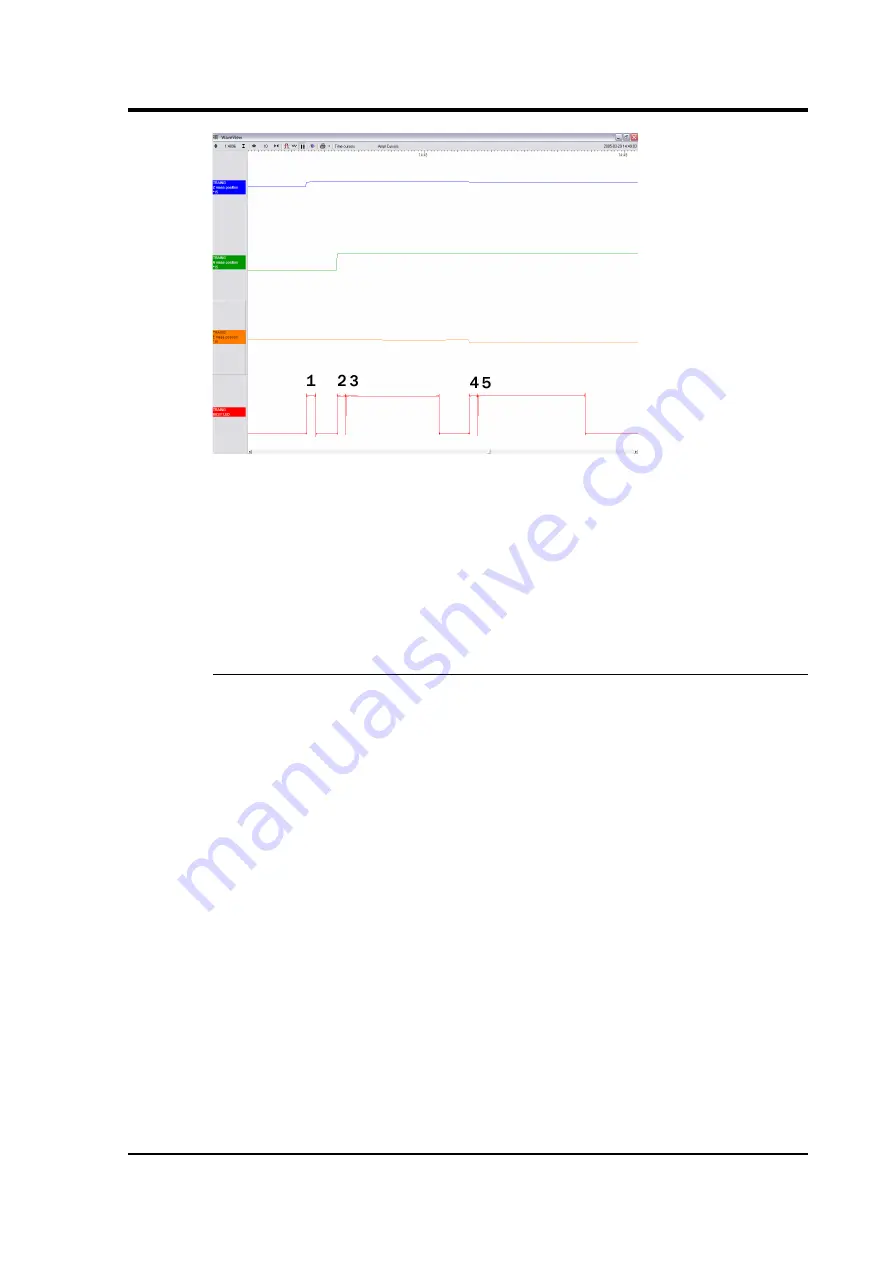
In the five-stage process, each mass in turn is locked with a motorised 

micrometer (stages 1, 2, 4), and the 

N/S and E/W sensor bases are tilted 

to their end stops (stages 3 and 5). At some point during each tilting 

stage, the position of the relevant mass will flip to one or other side.

The  

BUSY  LED is lit during each stage, but goes out briefly between 

stages, allowing you to follow the progress of the lock.

UNLOCK 

This command unlocks the sensor masses and prepares the instrument 
to begin operating.

If  

UNLOCK  is activated when the masses are already unlocked, the 

processor will lock them and attempt to unlock again. This is useful if 
you suspect that the locking procedure has failed.

During   the  

UNLOCK  procedure,   the   instrument   automatically 

performs a round of centring for each component.

November 2006

67

Summary of Contents for CMG-3TB

Page 1: ...proprietary to G ralp Systems Limited and may not be copied or distributed outside the approved recipient s organisation without the approval of G ralp Systems Limited G ralp Systems Limited shall no...

Page 2: ...The handheld control unit 19 Connections 20 Signal meter 20 Calibration and control 21 Banana plugs 21 The inclinometer monitor unit 21 2 6 Operating the hole lock 22 Engaging the hole lock 23 Disenga...

Page 3: ...g copies of the calibration pack 57 4 2 Calibration methods 58 4 3 Calibration with Scream 58 Sensor response codes 62 4 4 Calibration with a handheld control unit 62 4 5 The coil constant 63 5 Inside...

Page 4: ...data Sensor functions such as levelling and mass locking are carried out through a surface control box The 3TB s sensors are sensitive to ground vibrations in the frequency range 0 0027 50 Hz It outp...

Page 5: ...ncluding a breakout box and a number of additional optional control units which may be connected to the breakout box to perform installation and maintenance tasks For example a borehole or pit install...

Page 6: ...le digitizer allows you to construct a true digital borehole installation This has several advantages over a traditional borehole setup Digital signals are not subject to attenuation as they travel up...

Page 7: ...ing transmitting any stresses G ralp Systems hole locks are constructed to order from accurate measurements of your borehole at the depth you wish to install the instrument Either single jaw or three...

Page 8: ...contacts only the tips of the skids come into contact with the borehole providing three point contacts a single skid is combined with a pad to provide one line and one point contact or three studs pro...

Page 9: ...arate from that of the sensor and can be controlled from the surface using a hole lock control unit Once the sonde is installed the hole lock control unit may be removed Without power the hole lock wi...

Page 10: ...CMG 3TB held parallel to the axis of the borehole and prevented from twisting or slipping under the influence of ground vibrations 10 Issue C...

Page 11: ...eismometer in sections a cable to join the sensor to the breakout box the breakout box the hole lock control unit a cable strain relief mechanism a Handheld Control Unit HCU for monitoring sensor outp...

Page 12: ...ng if possible Do not kink or walk on the data cable especially on rough surfaces such as gravel nor allow it to bear the weight of the sensor Do not connect the instrument to power sources except whe...

Page 13: ...to prevent it from falling over This can be done either by using an assistant to hold the casing steady or by strapping it to a support such as a bench leg 3 Remove the packing caps from the top of th...

Page 14: ...le lock unit with the NORTH mark on the horizontal sensor housing Doing this will allow you to check the approximate orientation of the sensors at a glance The horizontal sensor consists of two distin...

Page 15: ...enly working round the instrument in several passes until the two sections are securely joined together 9 The vertical sensor now needs to be attached to the other end of the hole lock Remove the pack...

Page 16: ...nt has several sets of screws holding it together Only one set from each joint needs to be undone the set which was added during assembly For the joint between the vertical sensor and the hole lock th...

Page 17: ...CMG DM24 The DM24 digitizer is able to pass commands to the instrument from a Data Communications Module DCM or a computer running G ralp Systems Scream software allowing you to access all of the ins...

Page 18: ...sure that logic signals are reliably transmitted to the sensor Contact G ralp Systems for advice Note The breakout box looks very similar to other G ralp breakout boxes However its internal wiring is...

Page 19: ...centre the instrument hold down ENABLE and CENTRE buttons or the CENTRE switch for at least six seconds If the masses are locked the microcontroller will do nothing Otherwise it attempts to zero the...

Page 20: ...the breakout box When using this alternative power connection you should ensure you do not inadvertently connect two power supplies together Signal meter The upper section of the HCU contains a simple...

Page 21: ...own the ENABLE switch on the HCU together with the appropriate switch for the command you want to issue for at least six seconds Banana plugs The remainder of the HCU provides useful connections for e...

Page 22: ...from the analogue meters 4 If both tilts are within the green shaded region the instrument is close enough to vertical that it can be levelled and centred successfully If either output is in the red...

Page 23: ...ns power You should ensure that you provide the correct voltage to the hole lock control unit otherwise damage may result to the sensor 2 Open the MASS LOCK UNLOCK POWER ON OFF flap on the breakout bo...

Page 24: ...emove the hole lock power cable and control unit from the site Without power the hole lock will not be able to retract and the sensor will be secure Disengaging the hole lock To retract the jaw of the...

Page 25: ...Operator s guide 0 V To retract the jaw reverse the polarity so that the Hole Lock Motor Return pin is at 12 V and the Hole Lock Motor pin is at 0 V November 2006 25...

Page 26: ...pth gauge if possible or measure out the cable beforehand Most installations are equipped with a strain relief unit which consists of a metal arm that swings out from the load bearing cable to wedge a...

Page 27: ...kout box and Holelock Control Unit and attempt to retract the hole lock arm see Section 2 6 page 22 If this fails you should contact G ralp Systems Extend the arm once more 3 Fix the main lifting cabl...

Page 28: ...in relief mechanism using the linking cable provided 6 Using a small winch hoist up the sensor package and strain relief mechanism until both are hanging by the lifting cable with the strain relief me...

Page 29: ...22 to check that it fits your borehole The current drawn should dip slightly as the arm touches the casing then drop to zero when it is fully extended Check that the sonde is firmly anchored to the bo...

Page 30: ...he hole lock arm see Section 2 6 page 22 If you are installing a 3TB in a deep borehole the weight of the sensor will stretch the load bearing cable slightly Remember to allow for this when raising or...

Page 31: ...or in position This sand is suitable for use in both dry and damp boreholes In the procedure outlined below the sensor rests on a pad of sand around 300mm thick This pad will absorb any residual moist...

Page 32: ...a sufficient quantity of sand to fill the borehole to a depth of around 300mm 3 Connect the signal cable to the connector on top of the sensor Ensure that the O rings inside the housing are clean and...

Page 33: ...of the strain relief mechanism using the linking cable provided 7 Hoist up the sensor package and strain relief mechanism until both are hanging by the lifting cable with the strain relief mechanism e...

Page 34: ...or digitizer If you are installing a 3TB in a deep borehole the weight of the sensor will stretch the load bearing cable slightly Remember to allow for this when raising or lowering the sensor in the...

Page 35: ...fficiently close to vertical to be properly centred See section 3 5 page 46 for details 16 Calculate the volume of dry sand required to fill the gap between the sensor and the borehole liner to the le...

Page 36: ...ctions for each leg of the tripod The upper sections are pre attached to the head of the tripod the lower sections are supplied detached 1 Slide the lower sections all the way into the head with the r...

Page 37: ...between the legs If the loop is not provided you can make one by untwisting three outer strands from the 7 core cable crossing the two sets and pleating the three outside strands back around the remai...

Page 38: ...earing cable without the loop and screw it to the axle inside the winch using a 4 mm Allen key provided as shown 8 Attach the handle to the side of the winch opposite the ratchet mechanism and fasten...

Page 39: ...he drum Continue winding until the loop on the other end is as high as you need it to install the equipment If the ratchet prevents you from winding the cable on twist the metal boss in the DOWN direc...

Page 40: ...ion must also be followed Installations with AC power supplies If you are using mains outlet power or some other AC power distribution system we recommend installing a fully isolating transformer betw...

Page 41: ...ound line from the sensor should be connected to this plate The best local earth point in many installations is the borehole itself For this to work the borehole must have a conductive casing and be s...

Page 42: ...le is filled with salt water the instrument will be adequately grounded without any further action Fresh water is an inferior conductor In a dry or sand filled borehole or one with a non conducting ca...

Page 43: ...ad bearing cable is suitable for this purpose provided it is secured to the sensor s lifting loop with a metallic clamp as shown below This provides an additional firm contact between the sonde and th...

Page 44: ...ing between this sensor local earth line and ground lines for other parts of the system must be minimized Installations with DC power supplies G ralp sensors require a 24 V DC power supply In most cas...

Page 45: ...otection although some form of protection is always necessary External lightning protection The surface installation building and if possible the borehole also should be protected by lightning conduct...

Page 46: ...can lie closer to vertical 5 Connect a handheld control unit HCU to the sensor control unit if you have one 6 Unlock the sensor masses either by pushing the UNLOCK buttons of the borehole control unit...

Page 47: ...e components from the compass points you can instruct the digitizer to rotate the signals algorithmically Installing the Scream extension The Relative Orientation extension is supplied in the standard...

Page 48: ...OK 3 Drag the data files you have recorded into Scream A Replay Control window will open 4 Click the Increase Speed icon until the legend 128x in the picture above reads Max 5 Click the Pause icon to...

Page 49: ...twork 7 Double click on one of the selected streams or press ENTER A WaveView window will open 8 Drag the streams across the window so that the reference stream is at the top the N stream in the middl...

Page 50: ...is not using a standard N S channel but the auxiliary X channel If you are using a separate digitizer the warning will not appear If you get an error make sure the streams are in the right order in t...

Page 51: ...ith an estimated error You should see a coherence curve which is smooth and symmetrical If the curve is distorted either the surface data is too noisy or the data selection is too short The lower grap...

Page 52: ...arrowing the search range This is done in the two entry boxes on the Coherence vs Angle window the first denotes the centre of the new search and the second its range The program suggests suitable val...

Page 53: ...ce of error is in the installation of the reference sensor Applying automatic rotation You can configure a DM24 mk3 digitizer to apply an automatic rotation to the digitized data and output streams re...

Page 54: ...the digitizer to apply the rotation to instrument number 0 the first or only instrument Thus in the example above you would type 0 903 AZIMUTH to make the digitizer rotate signals by 90 3 degrees 3 Re...

Page 55: ...to velocity at 1 Hz in volts per m s Because the 40TB uses balanced differential outputs the signal strength as measured between the ve and ve lines will be twice the true sensitivity of the instrume...

Page 56: ...y response In practice it is possible to design a system transfer function with a very wide range flat frequency response The normalising constant A is calculated at a normalising frequency value fm 1...

Page 57: ...g correctly you can inject calibration signals into the system using a G ralp digitizer or your own signal generator and record the instrument s response Obtaining copies of the calibration pack Our s...

Page 58: ...to determine the response over the full frequency spectrum Injecting white noise into the calibration coil gives the response of the whole system which can be measured using a spectrum analyser You c...

Page 59: ...icon and select Control Open the Calibration pane 2 Select the calibration channel corresponding to the instrument and choose Broadband Noise Select the component you wish to calibrate together with a...

Page 60: ...s visible in the Waveview window 5 If you need to scale one but not another of the traces right click on the trace and select Scale You can then type in a suitable scale factor for that trace 6 Pause...

Page 61: ...e the Scream documentation for more information 9 Click OK The script will return with a graph showing the responsivity of the sensor in terms of amplitude and phase plots for each component if approp...

Page 62: ...unit If you prefer you can inject your own calibration signals into the system through a handheld control unit The unit includes a switch which activates the calibration relay in the seismometer and 4...

Page 63: ...accurately 1 Measure the acceleration due to gravity g at your location 2 Tilt the instrument slightly and measure its attitude and the gain of the mass position output for the component you wish to...

Page 64: ...nd face allow for simple and accurate assembly The base of each unit includes a double O ring to isolate the sensor from any pressure variations in the atmosphere The 3TB functions by monitoring the p...

Page 65: ...are sent as single ended circuits referred to analogue ground on the output plug The 3TB also receives control signals which are used to clamp and unclamp the masses and to run the motors which level...

Page 66: ...ines are high the control microprocessor goes into a power saving mode In routine operation the lines are controlled from the breakout box Handheld Control Unit or digitizer If you send control signal...

Page 67: ...is lit during each stage but goes out briefly between stages allowing you to follow the progress of the lock UNLOCK This command unlocks the sensor masses and prepares the instrument to begin operatin...

Page 68: ...ts level position This process takes rather longer At some point during this stage the mass may flip to the other side as seen in the green trace 5 The N S sensor mass is centred by applying pulses to...

Page 69: ...or and stops the centring process once it reaches its lowest offset This graph shows a typical centring process 1 The BUSY LED pulses to indicate that it is centring the Z component Each pulse corresp...

Page 70: ...d on these general principles The capacitative position sensor for each mass produces a voltage proportional to the displacement of the mass from its equilibrium position After amplification this volt...

Page 71: ...s a single capacitor in parallel with a resistor resulting in a single dominant pole at 0 033 Hz 30 s Below this frequency the response of the seismometer is flat to ground acceleration above it the r...

Page 72: ...damping constant of 0 707 1 2 The seismometer can be supplied with an equivalent resonant frequency of 0 033 Hz 30 s 0 01 Hz 100 s or 0 0083 Hz 120 s as required An active low pass filter provides a h...

Page 73: ...Operator s guide November 2006 73...

Page 74: ...spec plugs 02E 16 26P Column d The POWER connector on the breakout box a 10 way mil spec socket 02E 12 10S a b c d Function A H F Hole lock motor B b K Hole lock motor return C Z Z Inclinometer power...

Page 75: ...se ground The Acc Vel mode switch pin is used by the automatic centring process to switch the instrument temporarily into a mode where its response at normal frequencies is flat to acceleration and th...

Page 76: ...ity 1000 V m s2 Controls Mass locking and unlocking remotely operated Mass centring microprocessor controlled Mechanics and electronics Sensors 3 orthogonal sensors each 0 180 kg Lowest spurious reson...

Page 77: ...e value of spec would be 30 s 0 033 Hz Sensors are available with a range of sensitivities between 2 750 and 2 10 000 V m s Because centring locking and unlocking consume varying amounts of power it i...

Page 78: ...CMG 3TB 8 Revision history 2006 11 15 C Updated Scream and SOH added revision history 2005 05 12 B Original document 78 Issue C...

Reviews: