22
tower 3/1 20K tower 3/1 10K
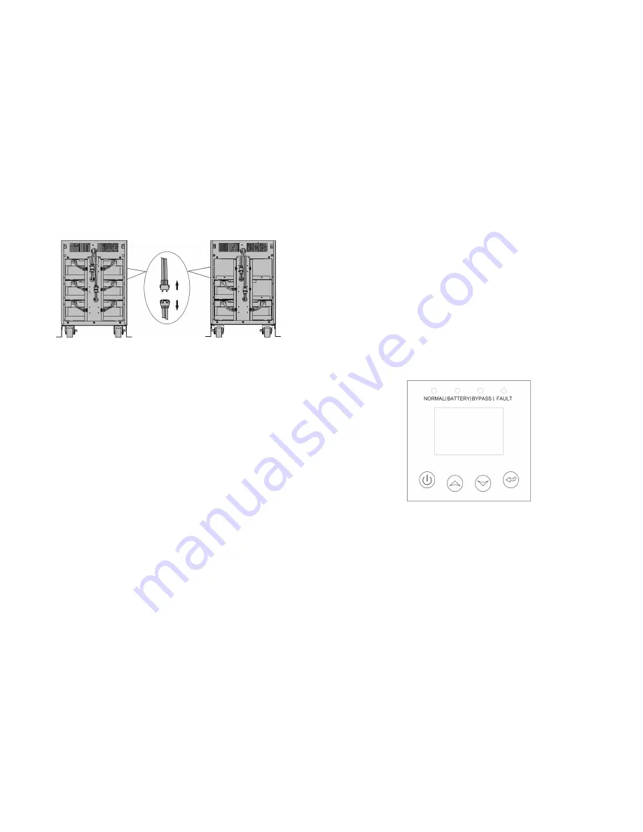
Fig. 4-7 Disconnect the internal battery pack DC connectors
2) A DC breaker must be connected between the external battery
pack and the UPS. The capacity of breaker must be not less than
the data specified in the general specification.
3) Set the external battery pack breaker in “OFF” position and
connect the batteries
(
24 pieces for tower 3/1 10K-20K, 20
pieces for tower 3/1 10k-31C) in series.
4) For tower 3/1 10K-20K, Connect the external battery pack to the
battery terminals. For tower 3/1 10K-31C model, Connect the
external battery pack to the battery anderson connector.
5) Reconnect the internal battery pack DC connectors, if you had
did step one.
3. Do not attempt to connect any loads to the UPS now. You should
connect the input power wire to the right position first. And then set
the breaker of the battery pack in the “ON” position. After that set
the input breaker in the “ON” position. The UPS begins to charge the
battery packs at the time.
23
5. Operation
5.1 Display Panel
The UPS has a four-button graphical LCD with dual color backlight.
Standard back-light is used to light up the display with white text and
a blue background. When the UPS has a critical alarm, the backlight
changes the text to dark amber and the background to red. Besides
the graphical LCD, the UPS has four colorized LEDs to provide you
more convenient info.
See Figure Below
Fig. 5-1 tower 3/1 10k-20K/tower 3/1 10K-31C On-line UPS Control Panel
Table 5-1 Control Button Functions


