


NS3000 Series User Manual
6.1.1 LED Indicator
The LEDs shown on the mini current path represent the various UPS power paths and show the
current UPS operating status. The status description of indicators is shown in table 6-2.
Table 6-2 Status description of indicator
Indicator
State
Purpose
Steady green
Rectifier normal
Flashing green
Rectifier starting, mains normal
Steady red
Rectifier fault
Flashing red
Mains abnormal
Rectifier
indicator
Off
Rectifier not operating
Steady green
Battery charging
Flashing green
Battery discharging
Steady red
Battery abnormal (battery failure, no battery or battery reverse) or
battery converter abnormal (failure, overcurrent or over temperature)
, EOD
Flashing red
Battery low voltage
Battery
indicator
Off
Battery and battery converter normal, battery not charging
Steady green
Load power supplied by bypass
Steady red
Bypass power abnormal or out of normal range, or static bypass
switch fault
Flashing red
Bypass voltage abnormal
Bypass
indicator
Off
Bypass normal
Steady green
Load power supplied by inverter
Flashing green
Inverter On, start, synchronization of standby (ECO mode)
Steady red
System power not supplied by inverter, inverter fault
Flashing red
System power supplied by inverter, inverter fault
Inverter
indicator
Off
Inverter not operating
Steady green
UPS output ON and normal
Steady red
UPS output overload and overtime, or output short, or output no
power supply
Flashing red
Overload output of UPS
Load
indicator
Off
No output of UPS
Steady green
Normal operation
Status
indicator
Steady red
Failure
6.1.2 Audible Alarm (buzzer)
There are two different types of audible alarm during UPS operation as shown in table 6-3.
Table 6-3 Description of audible alarm
Alarm
Purpose
Two short alarm with one
long alarm
when system has general alarm (for example: AC fault), this audible
alarm can be heard
Continuous alarm
When system has serious faults (for example: fuse or hardware fault),
this audible alarm can be heard
6.1.3 Functional Keys
There are 4 functional keys on operator control and display panel, which are used together with LCD.
The functions description is shown in table 6-4
Table 6-4 Functions of functional key
Functional key
Functions
EPO switch
To cut off the load power to shut down the rectifier, inverter, static bypass and
battery
HOME
To return the main menu
Left arrow and righ
arrow
Select options in the mian menu, switch over secondary meun pages, upward
and downward roll the histrical log, add and subtract the intered number
Enter key
confirm
6.2 LCD Display Type
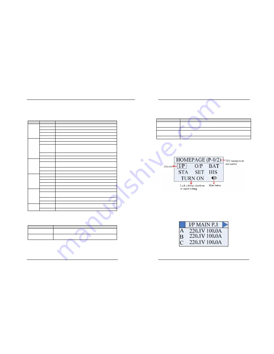
After UPS starting screen completes self-inspection, main display shown in fig. 6-2 appears. The
main panel display for 10KVA~30KVA type is provided with six main menus, turn on/off UPS, mute or not
button.
Fig. 6-2 Homepage display
6.2.1 Default Display
During the operation of system, if there’s no alarm in 2 min, the system will display default. After a
short delay, the backlight of LCD display goes off; press any key to reactivate the display. Default display
is homepage or brand display.
6.2.2 Data Display
The Input Data display as below (Press left and right arrow to select “I/P” , then press “ENTER”.):
Fig.6-3 I/P data display for 10KVA~30KVA UPS
In I/P data interface, you can not input or modify data, just view them.


