Gruppo Imar IVY 24 MR/MN Installation & Use Manual Download Page 5

3

DESCRIPTION OF THE BOILER
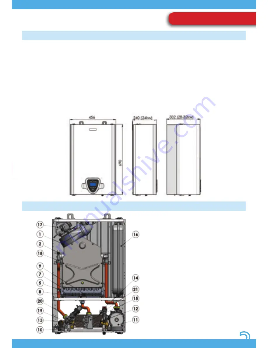
COMPONENTS

The Ivy range of boilers represents the best 

appliances available for domestic central 

heating and hot water production. Their 

essential but extremely modern and 

elegant lines, compact size, solidity, 

performance, reliability and safety place 

Ivy boilers in the category of appliances 

which are indispensable in every home. In 

creating the Ivy range of boilers we chose 

to design a system which could satisfy a 

wide range of needs, able to adapt itself 

to any situation and thus enlarging its 

field of application. Models ranging from 

24  to  32  kW  power  output  are  indeed 

available. The flexibility of the Ivy range of 

boilers is also increased by the possibility 

to configure the management program 

of the microprocessor fitted to the system. 

This allows to pass from a reduced number 

of functions and configurations which 

make using the device easy, immediate 

and effective to a complete configuration 

with  many  specific  options  enabled  as 

well as the possibility to interface with 

external control and regulation devices.

Ivy MR (whit rapid heat exchanger)

1) FUME EXTRACTOR 

2) SAFETY THERMOSTAT 

5) HEATING SENSOR 

7) BURNER 

8) IGNITION MONOELECTRODE 

9) EARTH ELECTRODE 

10) PRESSURE GAUGE 

11) CIRCULATOR UNIT 

12) DHW PRIORITY VALVE 

13) PRESSURE SENSOR (TRANSMITTER) 

14) SAFETY VALVE 

15) GAS VALVE 

16) EXPANSION TANK 

17) COMBUSTION GAS PRESSURE SWITCH 

18) PRIMARY HEAT EXCHANGER 

19) IMMERSION DHW SENSOR 

20) THREE-WAYS GROUP 

21) SECONDARY HEAT EXCHANGER

Pic. 1

Pic. 2

USE AND OPERATION

Summary of Contents for IVY 24 MR/MN

Page 1: ...ITALIAN DESIGN INSTALLATION COMMISSIONING USE AND MAINTENANCE MANUAL Wall mounted boiler with plate heat exchanger Monothermal A brand by G20 ENGINEERING...

Page 2: ......

Page 3: ...IVY 24 28 32 KW MR MN MONOTHERMAL BOILER MANUAL VERS 11 2017 REV 3...

Page 4: ...nual supplied with every boiler should be considered as an integral component as it contains instructions for the correct safe and appropriate installation use and maintenance of the system The manual...

Page 5: ...of boilers is also increased by the possibility to configure the management program of the microprocessor fitted to the system This allows to pass from a reduced number of functions and configurations...

Page 6: ...lative values to be displayed is extremely simple It is composed of a large backlit LCD which displays all symbols necessary for communicating the boiler s status in a simple and immediate way togethe...

Page 7: ...with transducer and it is possible to turn the boiler on by pressing BUTTON 1 at the MAIN MENU page In order to go back to the first page stand by press again BUTTON 1 Pic 5 2 By pressing BUTTON 4 th...

Page 8: ...are installed the following are displayed respectively the pressure of the central heating circuit with relative symbol the external sensor present symbol and the OT timer thermostat present symbol P...

Page 9: ...onal mode i e ready to supply the only service which it has been manufactured for Pict 7 3 SEASON SELECTION TEMPERATURE REGULATION Pic 7 1 Pic 7 2 Pic 7 3 Boilers for domestic hot water production It...

Page 10: ...ice for modifying the CH temperature is disabled Boilers for central heating only Only the temperature value for the single option which can be viewed on the display can be adjusted in central heating...

Page 11: ...e automatically based on the temperature measured by the suitably located sensor on the outside of the building Adjustments are made automatically to the central heating circuit temperature using a pr...

Page 12: ...transitory faults are possible Many of these are recognized and cause a temporary block which is automatically reset once the condition causing the fault has stopped Some of these provide for the poss...

Page 13: ...ter temperature too high Boiler locked Degas CH system Check CH system pressure Check CH system circulation Check combustion adjustmen E10 Central heating system pressure too HIGH 2 7 bar Boiler locke...

Page 14: ...heat exchanger 2 Burner 3 Gas valve 4 Three way valve 5 Safety valve 6 Filling loop cock 7 Hot water priority turbine 8 Secondary heat exchanger 9 Circulator unit 10 Expansion tank 1 Primary heat exc...

Page 15: ...UMP LIVE PUMP NEUT FAN LIVE FAN NEUTRAL NEUTRAL LIVE GND SIGN 5VDC PRESSURE SENSOR 3WAY VALVE MOTOR 1 6 3 4 M0900 M0901 M0100 M0101 M0904 M0902 M5 M3 1 1 1 1 1 1 EA EA TERRA M0900 M0901 M0100 M0101 M0...

Page 16: ...d maintenance manuals and observing the general inspection and maintenance conditions General requirements Installation must only be performed by qualified and licensed personnel They also assume resp...

Page 17: ...ly prepared holes then hang the boiler inserting the hooks of the plugs in the specific holes Fasten the template so that its axis coincides perfectly with that of the boiler 750 MURO WALL DIMENSIONE...

Page 18: ...Pic 20 Pic 21 LAYOUT OF CONNECTIONS 24 KW 28 32 KW...

Page 19: ...ORPROPERTY DUE TO OPERATION OF THE SAFETY VALVE DO NOT USE THE PLUMBING PIPEWORK CONNECTIONS AS EARTH POINTS FOR ELECTRICAL EQUIPMENT CONNECTING FILLING COCK FOR CENTRAL HEATING ONLY BOILERS In order...

Page 20: ...ore connecting the boiler to the mains gas check that it is designed to function with the available type of gas Thoroughly flush all the gas pipes to remove any residues which could compromise correct...

Page 21: ...witch installed before it Remove the lower cover by removing the four screws turn the instrument panel to the open position Remove the rear case cover by unscrewing the 4 screws Identify the terminals...

Page 22: ...isted on the technical data plate and summarised below C12 concentric wall flue The pipes may also be split but the outlets must be exposed to similar wind conditions C32 concentric vertical flue with...

Page 23: ...it flue system is composed of one pipe for combustion gas evacuation connected to the fan outlet and one for the air intake connected to the hole on the roof of the sealed chamber The system provides...

Page 24: ...lar gasket d 60 12 Gasket d 80 The maximum possible length therefore depends on the components used to create the line and can be determined by adding the Equivalent lengths for each individual compon...

Page 25: ...fan and flue duct for systems of minimum or intermediate length The size of the diaphragm depends on the The detected value shall not be less than shown in the table EXHAUST TECHNICAL FEATURES SUMMARY...

Page 26: ...NG FROM APPLICABLE LEGISLATION AND REGULATIONS TO THE LETTER ONLY USE APPROVED COMPONENTS FOR AIR INTAKE AND COMBUSTION GAS EVACUATION SYSTEMS WHICH ARE OF THE CORRECT DIMENSIONS AND PURPOSELY DESIGNE...

Page 27: ...burner Check that the boiler ignites turns off and functions correctly Visual check for leaks in gas and water pipes and unions Check that the safety devices are operational This function allows the b...

Page 28: ...LER HAVE BEEN OBSERVED If the function remains activated for long periods of time an increase in pressure may occur in correspondence with the system s terminals All safety measures are active when in...

Page 29: ...plicable legislation and regulations in particular That a gas shut off valve is installed immediately before the device This must have a YELLOW valve handle and must be placed in a position which allo...

Page 30: ...connect it with silicone tubing to the input of a differential manometer with an appropriate range at least 0 Check that all preliminary indications and checks specified have been carried out Activate...

Page 31: ...ine which could lead to excessive pressure drops e g too many bends changes of direction excessively long or countersloping sections etc Consult the gas company on the specified minimum supply pressur...

Page 32: ...LET SCREW UNTIL IT SEALS Press the gas valve regulation screws cover closed Return the instrument panel to its operating position fastening if necessary Refit the lower cover fastening it with the scr...

Page 33: ...rews together with any previously removed deflectors and conveyors Replace and close the combustion chamber cover Reconnect the ignition electrode cable located in the front Replace and close the seal...

Page 34: ...alue of the parameter referred to by that page is displayed normally In this mode it is possible to scroll through the pages for all parameters and read the relative values but without the possibility...

Page 35: ...te curve parameter 20 10 0 P9 Type of system pressure measurement device 0 none 1 0 5 2 5 V transducer B type 2 0 5 3 5 V transducer A type 3 pressure switch 4 flow switch P10 ALL PARAMETER MODIFICATI...

Page 36: ...2 Low temperature 1 A3 Plate heat exchanger preheating 0 not enabled 1 enabled 0 A4 Storage tank preparation temperature Spboll sp sani a4 5 20 15 A5 DHW storage tank hysteresis temp for burner igniti...

Page 37: ...or the EASY CONTROL Open Therm see wire scheme at page 15 Connection x13 Whenever necessary replace the TA cable and connect it directly to the slot present in the PCB case as follows Power the boiler...

Page 38: ...slots Pict 41 Run the cable and hold it in position with the cable grip at the edge of the case Position the cable running it under the cable gripping tabs on the side of the case Close the case cover...

Page 39: ...me comfort to be maintained while making significant savings in gas consumption It is possible to adapt the boiler s response based on the climatic conditions present by configuring the slope of the c...

Page 40: ...low circuit is 6 C circulation is activated the diverter valve when present switched to the CH circuit and the burner lit at minimum power When the temperature measured by the sensor reaches 30 C the...

Page 41: ...at stress in case at the end of a DHW intake the heat exchanger temperature is too high a heat disposal function by fan ignition is activated This function remains active until the temperature values...

Page 42: ...head mwc 5 0 6 0 6 5 DOMESTIC HOT WATER Continuous draw T 25 C l min 13 5 14 5 16 6 Max DHW pressure bar 10 0 10 0 10 0 Min DHW pressure bar 0 5 0 5 0 5 Min max DHW temp adjustment C 30 60 30 60 30 60...

Page 43: ......

Page 44: ...MADE IN ITALY G20 ENGINEERING SRL Loc Campogrande 13 29013 CARPANETO PIACENTINO PC Italy phone 39 0523 850513 fax 39 0523 850712 www aircontrol pc com www g20engineering com A brand by G20 ENGINEERING...

Reviews: