MAINTENANCE REDI-FLO2®
Winding Resistance
Insulation Resistance
OHMMETER
R x 000
R x 000
R x 000
R x 000
R x 000
R x 000
R x 000
R x 000
Lead Length
Ohm Value
0 ft ..................... 3.0 - 3.5
W
50 ft ..................... 3.6 - 4.1
W
75 ft ..................... 3.9 - 4.4
W
100 ft ..................... 4.2 - 4.7
W
125 ft ..................... 4.5 - 5.0
W
150 ft ..................... 4.8 - 5.3
W
175 ft ..................... 5.1 - 5.6
W
200 ft ..................... 5.4 - 5.9
W
250 ft ..................... 6.0 - 6.5
W
300 ft ..................... 6.6 - 7.1
W
Turn the power off and disconnect the mo-
tor lead from the converter. Using an ohm-
meter, set the scale to R X 1. Zero-adjust
the meter and measure the resistance be-
tween any two power conducting leads
(prongs on the motor lead plug).
If the ohm value is too low, the motor may
be shorted. If too high, the motor windings
or the leads may be open.
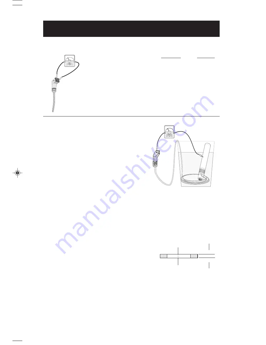
Turn the power off and disconnect the motor lead from the
converter. Use a 500V megohmmeter or megger (1 Meg =
1 M = 1 million). Zero-adjust the meter and measure the
resistance between any power conducting leads (prongs on
the motor lead plug) and ground. If the pump has been
removed from the well, a good way to test this (as shown at
right) is to submerge the motor lead and Redi-Flo2® pump
in a bucket of water. Touch one lead of the megohmmeter to
the pump and one to a motor lead.
If the ohm value is lower than 1.5M
W
on any lead other than
ground, the motor or lead is defective and must be replaced.
Checking Components For Wear
The pump components should be periodically checked to ensure they are still within their
minimum operating tolerances (illustrated below).
Impeller (position 5) ...................... The impellers should show no visible wear.
Guide Vane (position 3) ................ The guide vanes should show no visible wear.
Wear Ring (position 4) .................. The minimum thickness ("A" in the illustration)
....................................................... should never be less than 1.0 mm.
In addition, visually check all components for cracks, corrosion, or wear.
Storage Requirements
The pump should be thoroughly cleaned before storage to ensure no contamination is present.
Both the pump and the converter should be stored in a clean and dry area in the following
temperature range:
1°C to +50°C
or
34°F to 120°F
▲
▲
A
MEGA OHMMETER
Page 23
MAINTENANCE REDI-FLO4
VARIABLE PERFORMANCE PUMPS
Insulation Resistance
Turn the power off and disconnect the motor lead from the
Redi-Flo VFD. Use a 500V megohmmeter or megger (1 Meg
= 1 M = 1 million). Zero-adjust the meter and measure the
resistance between any power conducting lead (prongs in
the motor lead plug) and ground. If the pump has been
removed from the well, a good way to test this (as shown at
right) is to submerge the motor lead and pump in water.
Touch one lead of the megohmmeter to the pump and one
to a motor lead.
If the ohm value is lower than 1.5M
W
on any lead other than
ground, the motor or lead is defective and must be replaced.
Winding Resistance
Lead Length
Ohm Value
0 ft ..................... 2.75 - 3.35
W
50 ft ..................... 2.90 - 3.50
W
100 ft ..................... 3.05 - 3.65
W
150 ft ..................... 3.20 - 3.80
W
200 ft ..................... 3.35 - 3.95
W
250 ft ..................... 3.50 - 4.10
W
300 ft ..................... 3.65 - 4.25
W
350 ft ..................... 3.80 - 4.40
W
400 ft ..................... 3.95 - 4.55
W
450 ft ..................... 4.10 - 4.70
W
500 ft ..................... 4.25 - 4.85
W
550 ft ..................... 4.40 - 5.00
W
600 ft ..................... 4.60 - 5.20
W
Turn the power off and disconnect the motor
lead from the Redi-Flo VFD. Using an ohmme-
ter, set the scale to R X 1. Zero-adjust the
meter and measure the resistance between
any two power conducting leads (prongs in the
motor lead plug).
If the ohm value is too low, the motor may be
shorted. If too high, the motor windings or the
leads may be open.
Pump & Motor Inspection
There is no periodic maintenance required for Redi-Flo4™ products. Should a problem
develop, the following inspections should be performed:
If the pump is operating at a decreased capacity and the pump end does not appear to be
the cause, the motor should be checked. Remove the pump end from the motor first by
loosening and removing the four
1
¤
2
" nuts and pulling the pump end off the motor. Examine
by following the checklist below:
1. Check motor and pump shaft rotation: spin the shaft by hand, it may be tight
at first but should turn smoothly once started. If pump or motor does not turn
freely, replace as necessary.
2. Check the fluid level inside the motor as described below. Replace and refill
as necessary.
a. Turn the motor upside-down and remove the fill screw located in the center
on the bottom.
b. Water should be visible through fill hole, refill by injecting deionized
water as needed.
c. Rotate shaft to work out air pockets.
d. Tighten screw firmly taking care not to strip the screw threads.
3. Inspect the outside of motor and lead for cracks, dents, bulges, burns, etc.
4. Check the winding and insulation resistance of the motor and lead as
described below:
Page 24
TR'sVFDIO.p65
5/31/00, 9:02 AM
13


