


English (GB)
6
4.4 Pump
The pump is a non-self-priming, single-stage Grundfos HSEF
standard pump with volute casing. It has an radial suction port
and a radial discharge port with ANSI B 16.5 compliant flanges.
For technical data see page 24 chapter
.
The impeller diameter can be reduced to customise the pump
performance to a certain duty point. This means that the actual
impeller diameter differs from the standard diameter stated in
sales catalogues, data sheets, etc. The actual impeller diameter
is stated on the pump nameplate.
The HSEF pump is equipped with a stuffing box seal.
4.5 Engine
The pumps are driven by a stationary 4-stroke diesel engine from
John Deere or Doosan which has been specially adjusted to the
pump drive requirements of Clarke UK Ltd.
The rated engine power is adapted to the power requirement of
the pumps. The adjustment is made via the engine speed and
consequently this must not be changed. See appendix page 27
and section
the diesel engines and the individual pumps. Depending on
performance, the engines have a turbocharger and, if necessary,
also a charge air cooler.
The engine is cooled via a heat exchanger in the water-cooled
John Deere and Doosan engines. The coolant is led to the heat
exchanger via a pipe connected to the discharge port of the
pump.
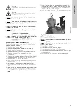
5. Identification
5.1 Pump
5.1.1 Nameplate
The nameplate shows all important data of the pump. It is
attached to top of the pump.
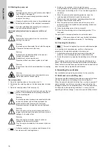
Fig. 4
Nameplate of a HSEF pump with FM approval
5.2 Pump set
5.2.1 Nameplate
The nameplate shows all important data of the pump set. It is
attached to the base frame.
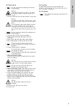
Fig. 5
Nameplate of an FM pump set
Caution
The fuel injection pump has been set from factory,
and the setting must not be changed.
TM
06 24
28 421
4
Pos.
Description
1
Pump type and model
2
Number of stages
3
Actual impeller diameter [mm]
4
Serial number
5
Rated flow Q [l/min]
6
Rated head H [m]
7
Rated speed n [rpm]
8
Head at 150 % flow [m]
9
Maximum operating pressure [bar]
10
Maximum pump power [kW]
11
Maximum suction pressure [bar]
12
Manufacturer
13
Approval
CENTRIFUGAL FIRE PUMP
HORIZONTAL SPLIT - CASE
IMP.DIA
SERIAL
MODEL
STAGE
RATED CAPACITY
RATED PRESSURE
RATED APM
MAX. POWER
MAX. SUCTION
PRESSURE
150% PRESSURE MAX. PRESSURE
4
3
2
13
5
8
9
1
7
10
6
11
12
T
M
06
19
43
50
1
4
Pos.
Description
1
Type designation
2
Product number
3
Serial number
4
Engine type
5
Impeller diameter [mm]
6
Rated flow rate Q [m
3
/h]
7
Head H [m]
8
Rated engine power P2 [kW]
9
Rated speed n [min
-1
]
10
Weight [kg]
11
Country of origin
12
Production date (year and week)
13
CE mark
14
Manufacturer
FIRE FIGHTING SYSTEM
Description:
Product number:
Main supply:
Impeller diameter:
Made in Germany - P1
Q:
P
2
:
kW
Week(yy.ww):
H:
n:
W:
m
kg
Serial number:
m /h
mm
Barcode:
min
-1
3
PN
Grundfos Pumpenfabrik GmbH Willy - Pelz - StraBe 1.5 23812 Wahlstedt GERMANY
1
2
4
5
6
8
11
13
3
7
9
10
12
14


