


English (GB)
11
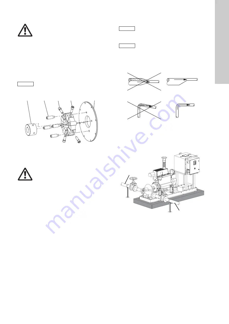
Checking the alignment
1. Disconnect the negative pole of the starter battery.
2. Remove the coupling guard.
3. Check the alignment according to
the installation and
operating instructions for the coupling.
4. Refit the coupling guard.
5. Reconnect the negative pole of the starter battery.
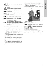
Aligning pump and engine
Fig. 14
Axial and radial fixation of the clamping hub of the
coupling
6. Align the coupling according to the installation and operating
instructions for the coupling.
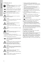
6.5 Pipe connection
The pipes must be installed as straight as possible and be of an
adequate size. Take the pump inlet pressure into consideration.
Install the pipes so that air locks are avoided. This applies
especially to the suction side of the pump. See fig. 15.
Fig. 15
Installation of pipes
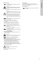
Secure the pipes close to the pump on the suction and discharge
side with pipe brackets attached to the building (wall, ceiling,
floor). See fig. 16.
The pipes should lie true against the pump flanges without being
stressed. Otherwise, the pump may be damaged.
Fig. 16
Fixing points of the pipes
Install isolating valves on both sides of the pump.
Connect the suction pipe to suction pump port and the discharge
pipe to the discharge pump port.
6.6 Priming tank and test pipe
If the pump set is supplied from a storage tank and the suction
height is negative, install a pump priming tank on the suction side
in accordance with local regulations. See also the standard
applying to the pump set.
Install a test pipe running from the discharge pipe to the storage
tank. The discharge pipe and the test pipe must be fitted with
isolating valves.
If the pump set is fed directly from the public water supply, the
test pipe must have a free outlet according to the standard
applying to the pump set.
Warning
Disconnect the battery cable before you remove the
coupling guard.
Beware of the sharp edges of the coupling guard.
Wear protective gloves.
Caution
Axial and radial screws can be reused maximum
three times.
Do not use threadlocker as it may damage the rubber
material.
T
M
04
00
58
49
07
Warning
After checking or adjusting the alignment, fit the
coupling guard.
1
4
2
5
3
Caution
The pipework must not stress the pump housing or
transfer any forces to the pump housing.
See permissible flange forces and torques in section
Note
The discharge pipe must have a port for venting and
priming the pump. See section
.
TM
00
22
63
33
93
TM
06
18
64
33
14
Discharge pipe
Suction pipe


