Grundfos Fire HSEF 10-20 Installation And Operating Instructions Manual Download Page 18

English (GB)

18

8.3 Starting the pump set

Additional safety instructions for pump set with diesel 
engine

General procedure

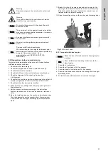
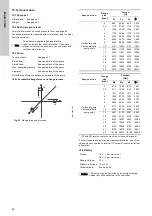
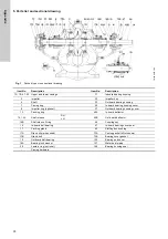
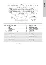
1. Open the isolating valve on the suction side (1).
2. Check that the isolating valve on the discharge side is closed 

(11).

3. Open the isolating valve of the test pipe (9).

4. Switch on the controller (14) and start the pump.

See installation and operating instructions for the controller.

5. Slowly open the isolating valve (11) on the discharge side of 

the pump.

6. When the pump reaches operating pressure, open the 

isolating valve sufficiently to reach the duty point.

7. Measure and read the relevant operating parameters and 

compare them with the rated values.

8. Stop the pump via the controller and set the pump set to 

automatic mode. See installation and operating instructions 
for the controller.

9. Close the isolating valve of the test pipe (9).
10. Check that the isolating valve at the discharge side (11) is 

fully open.

The pump set is now operational and in automatic mode.

8.4 Checking the function

In connection with commissioning, perform a final test run 
according to the standard applying to the pump set:
1. Activate the automatic startup command by lowering the 

pressure in the discharge pipe with a closed fuel valve.

2. Lower the pressure by opening the isolating valve of the test 

pipe.

Every starting cycle consists of a starting phase followed by a 
pause. A failure warning activates after six failed start attempts. 
When the fuel valve has been opened and the fault indication has 
been removed, the pump should start properly.

9. Operating the controller

See installation and operating instructions for the controller.

9.1 Shaft seal run-in (stuffing box)

The pumped liquid lubricates the seal faces, meaning that there 
will be a certain amount of leakage from the stuffing box.
When the pump is started for the first time, or when a new shaft 
seal is installed, a certain run-in period is required before the 
leakage is reduced to an acceptable level. The time required for 
this depends on the operating conditions, i.e. every time the 
operating conditions change, a new run-in period will be started.
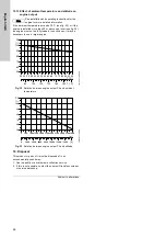
Warning
Some pump sets have a sound pressure level higher 
than 70 dB(A). See page 28. 
In these cases, wear hearing protection when the 
pump set is running.

Note

Observe the safety instructions in the installation and 
operating instructions of the individual components.

Note

See also installation and operating instructions for 
the controller and diesel engine.

Warning
Remove the fuel canisters from the room before 
starting the pump set.

Warning
Fuel vapours are flammable. Do not start the engine 
if there are fuel vapours in the room.

Warning
Exhaust must be directed safely to the open air 
through the exhaust system. 
Exhaust must not escape indoors.
Operation without an exhaust system is not safe.

Warning
The pump set must not be started without a coupling 
guard.

Warning
Make sure that persons cannot accidentally come 
into contact with hot exhaust pipes.

Note

Open the fuel valve on the fuel tank and vent the fuel 
system. See installation and operating instructions 
for the diesel engine.

Warning
Fuel escaping under pressure can penetrate the skin 
and cause serious injuries. Always release the 
pressure before disconnecting the fuel pipes. 
Repressurise when the pipes have been tightened.

Warning
When the pump set is primed, pressurized and the 
engine is started, check the pump set for any kind of 
leakage of oil, water or fuel.

Warning
When the engine is started, check for exhaust 
leakage and abnormal noise level.
Stop the engine immediately if the exhaust system is 
leaking. 

Note

Collect excess fuel in a container and dispose of it in 
accordance with local regulations.

Note

If the pump does not start, see the fault indications 
on the controller and section 

13. Fault finding

.

Note

This section applies to pump sets with diesel engine.

Summary of Contents for Fire HSEF 10-20

Page 1: ...Fire HSEF FM Europe Diesel powered firefighting system Installation and operating instructions GRUNDFOS INSTRUCTIONS ...

Page 2: ...10 2 Automatic operation 19 10 3 Manual operation 19 10 4 Emergency operation 19 10 5 Weekly test run 19 11 Shutdown 19 12 Maintenance 19 12 1 Preparation before maintenance 20 12 2 Maintenance interval 20 12 3 Pump set 20 12 4 Shaft seal 20 12 5 Bearings 20 12 6 Fuel filters 20 12 7 Battery 20 12 8 Diesel engine 21 12 9 Coupling 21 12 10 Controller 21 13 Fault finding 22 13 1 Pump set with diesel...

Page 3: ...tial damage is excluded The start of the warranty period is to be verified 3 2 1 Engine warranty In order to ensure that warranty issues can be handled correctly every engine needs to be registered at the manufacturer s website 1 Go to http www clarkefire com 2 Choose category SERVICE PARTS WARRANTY 3 Choose Warranty 4 Choose between two categories either Clarke John Deere Online Warranty Registra...

Page 4: ... boosting The control cabinet must not be used to supply voltage to other devices 4 3 Pump set The complete pump set consists of a pump a diesel engine and a controller A flexible coupling connects engine and pump All components are adapted to each other and mounted on a common base frame ready for installation The base frame has holes for fastening lifting equipment and holes for attaching it to ...

Page 5: ...Generator with V belt and cover 2 Pump 16 Starter 3 Coupling with coupling guard 17 Starter relay 4 Engine complete 18 Starter batteries 5 Controller 19 Diesel injection pump 6 Fuel tank 20 Fuel filter 7 Tank cap 21 Fuel delivery pump 8 Manual filling pump 22 Speed setting 9 Fuel valve hidden 23 Stop lever 10 Drain screw on fuel tank hidden 24 Oil dipstick 11 Exhaust pipe 25 Oil filter 12 Heat exc...

Page 6: ...ted to the discharge port of the pump 5 Identification 5 1 Pump 5 1 1 Nameplate The nameplate shows all important data of the pump It is attached to top of the pump Fig 4 Nameplate of a HSEF pump with FM approval 5 2 Pump set 5 2 1 Nameplate The nameplate shows all important data of the pump set It is attached to the base frame Fig 5 Nameplate of an FM pump set Caution The fuel injection pump has ...

Page 7: ...electric powered H Hoyer S Siemens O Other Approval standard A FM approved and according to NFPA 20 B FM UL listed and according to NFPA 20 C LPCB listed and according to BS EN 12845 D CNBOP approved and according to VdS CEA 4001 E Non listed and according to VdS CEA 4001 F Non listed and according to NFPA 20 G Non listed and according to CEA 4001 H Non listed and according to EN 12845 I APSAD ref...

Page 8: ... the engine starts The louvres must be dimensioned according to NFPA 20 This will ensure an adequate amount of fresh air to remove engine heat and combustion from the room Warning You must not disconnect any parts of the entire pump set without guidance by Grundfos Service Warning Use personal protective equipment when carrying out commissioning maintenance and test in order to prevent or minimise...

Page 9: ...ng gap must be grouted with a suitable shrink free hardening and high strength or reinforced undercast i e Pagel V1 or Eurogrout Premium to have a force fit connection between the base frame and the foundation Before grouting the undercast align the pump set by means of the adjusting screws used for the base frame See fig 9 Fig 9 Aligning the pump set For grouting the undercast make a shuttering o...

Page 10: ...fly wheel The pump shaft is pushed on axially and fixed radially with four screws See fig 13 For further information see the installation and operating instructions for the coupling Fig 13 Connection of pump engine Warning Lift the pump set by means of the lifting eyes of the base frame Never use the lifting eyes of the individual components Use only suitable lifting equipment in proper condition ...

Page 11: ...n pipe to suction pump port and the discharge pipe to the discharge pump port 6 6 Priming tank and test pipe If the pump set is supplied from a storage tank and the suction height is negative install a pump priming tank on the suction side in accordance with local regulations See also the standard applying to the pump set Install a test pipe running from the discharge pipe to the storage tank The ...

Page 12: ...xhaust port of the engine The exhaust port is covered for transportation by a plastic plug which must be removed before connecting the exhaust pipe See arrow in fig 19 The flexible connection on the engine must not be used to compensate for misaligned pipework The minimum diameter of the exhaust pipes must not be smaller than the exhaust port of the engine Fig 19 Exhaust port of the engine TM06 24...

Page 13: ...eparate concrete foundations must be in same level h1 h2 Placing the pump set 1 and fuel tank 2 at the same level ensures gravity supported feeding of fuel to the high pressure fuel pump at the engine See fig 20 The fuel tank must be fastened to the foundation with the mounting brackets Fig 20 Example correct installation of fuel tank Note Observe the standards when sizing and installing a separat...

Page 14: ... is stored in the base frame Fig 23 Fuel level indicator Installing the fuel level indicator 1 Remove the plastic cap from the connection on the top of the fuel tank 2 Adjust the indicator disc on the display to equal 100 when the weight is in top 3 Install the mechanical fuel level indicator Ensure that the display is facing the same direction as the controller 6 12 Fuel hand pump The pump set is...

Page 15: ...ive pole of battery 1 2 Connect the negative pole of battery 1 The positive pole is marked with red and the negative pole with black Proceed in the same way with battery 2 See fig 26 Fig 26 Connecting the batteries 12 V version 24 V version One battery set consists of two batteries connected in series at the factory 1 Connect the positive pole of battery set 1 2 Connect the negative pole of batter...

Page 16: ... reducer 11 Indicating gate valve or butterfly valve discharge control valve 20 Check valve jockey pump discharge not displayed 3 Suction pressure gauge 12 Flowmeter 21 Isolation valve jockey pump discharge 4 Discharge pressure gauge 13 Indicating gate valve or butterfly valve flowmeter 22 Check valve FDC 5 Automatic air release 14 Pump controller 23 Fire department connection 6 Pressure relief va...

Page 17: ...to evacuate any air trapped inside the impeller passages 12 Close the isolating valves on the suction and discharge sides Fig 29 Air relief valve 8 2 1 Pump set with diesel engine 1 Check the V belt tension 2 Check the oil level and refill if necessary 3 Check the level of coolant and refill if necessary 4 Check that all hose connections in the cooling circuit are tight and leakage free 5 Fill the...

Page 18: ...e first time or when a new shaft seal is installed a certain run in period is required before the leakage is reduced to an acceptable level The time required for this depends on the operating conditions i e every time the operating conditions change a new run in period will be started Warning Some pump sets have a sound pressure level higher than 70 dB A See page 28 In these cases wear hearing pro...

Page 19: ...ng instructions for the controller and diesel engine Note The pump set will not be shut down in case of disruptions Caution Do not leave the pump room during manual operation Observe all operating and fault indications as the pump set will not stop automatically in case of fault e g too high cooling water temperature or too low oil pressure Note This function is only available for pump sets with d...

Page 20: ... the installation and operating instructions for the engine We recommend that you replace the tank fuel filter at the same time 12 7 Battery The batteries must be dry under all operating conditions The liquid level in the batteries must be maintained The water used for filling must be distilled water Check the health of the battery by using a refractometer or similar tool 12 7 1 Battery replacemen...

Page 21: ... the pump and driver once a year See section 6 4 Alignment 12 10 Controller Note See also installation and operating instructions for the diesel engine Warning During and after operation surfaces components and working materials of the diesel engine can be very hot Warning Fuel vapours are flammable Therefore never top up fuel when the engine is running or when the engine is warm Do not inhale fue...

Page 22: ...ervice instructions for the pump e Pump stressed by the pipework Mount the pump so that it is not stressed Support the pipes See section 6 5 Pipe connection f Defective bearings Replace bearings g Defective coupling Replace the coupling h Foreign bodies in the pump Clean the pump and remove foreign bodies 3 Leaking pump housing a Pump stressed by the pipework Mount the pump so that it is not stres...

Page 23: ...pes 7 Oil pressure is too high or too low when engine is running a Oil filter blocked Replace the oil filter See installation and operating instructions for the diesel engine b Water or fuel in the oil Change oil See installation and operating instructions for the diesel engine c Oil level too low too high Refill with oil or drain off oil See installation and operating instructions for the diesel ...

Page 24: ...TM06 2665 4514 FZ FX MX Fy My MZ Grey cast iron Flange size inch Forces N Fx Fy Fz ΣF Horizontal pump x axis parallel to pump shaft 2 890 2224 890 2555 2 5 1112 2780 1112 3194 3 1334 3336 1334 3832 4 1779 4448 1779 5110 5 2224 5560 2224 6388 6 2669 6672 2669 7666 8 3559 8896 3559 10221 10 4137 10364 4137 11901 12 4430 11103 4430 12749 14 4724 11841 4724 13596 16 5018 12580 5018 14444 18 5311 13318...

Page 25: ...y an arrow on the pump housing 15 11 Liquid and ambient temperature Liquid temperature The pump is designed for liquid temperatures up to 120 C Ambient temperature The maximum permissible ambient temperature depends on the driver and controller See installation and operating instructions for the driver and controller 15 12 Relative air humidity The relative air humidity must not exceed 80 Otherwis...

Page 26: ...nd altitude 16 Disposal This product or parts of it must be disposed of in an environmentally sound way 1 Use the public or private waste collection service 2 If this is not possible contact the nearest Grundfos company or service workshop Subject to alterations Note See installation and operating instructions for the engine for more detailed information TM03 4718 2606 TM03 4717 2606 20 25 30 35 4...

Page 27: ...NSI 5 750 149 1800 HSEF 6 17 JU6H UF52 8 6 ANSI 5 750 157 1760 HSEF 6 17 JU6H UF62 8 6 ANSI 5 766 179 1780 HSEF 6 17 JU6H UF30 8 6 313 ANSI 5 750 119 1760 HSEF 6 17 JU6H UF30 8 6 ANSI 5 750 118 1760 HSEF 6 17 JU6H UFABL0 8 6 ANSI 5 750 129 1760 HSEF 6 17 JU6H UF52 8 6 313 ANSI 5 750 157 1760 HSEF 6 17 JU6H UF62 8 6 ANSI 5 766 179 1780 HSEF 6 14Q JU6H UF50 8 6 277 ANSI 5 750 157 1760 HSEF 6 14Q JU6...

Page 28: ...rundfos JU6H UF52 Contact Grundfos JU6H UF62 Contact Grundfos HSEF 8 15A DP6H UFKA70 Contact Grundfos DQ6H UFKA50 Contact Grundfos DR8H UFKA40 Contact Grundfos HSEF 8 17W JU6H UFKAS0 Contact Grundfos DP6H UFKA50 Contact Grundfos DP6H UFKA70 Contact Grundfos HSEF 8 17Q DQ6H UFKA50 Contact Grundfos DQ6H UFKA60 Contact Grundfos HSEF 8 20G DQ6H UFKA60 Contact Grundfos DQ6H UFKA88 Contact Grundfos DQ6H...

Page 29: ...6 125 8 9500 M20 5 125 8 8500 M20 HSEF 5 12 6 125 8 9500 M20 5 250 8 9250 M20 HSEF 5 14 6 125 8 9500 M20 5 125 8 8500 M20 HSEF 5 14N 6 125 8 9500 M20 5 125 8 8500 M20 HSEF 6 14Q 8 125 8 11750 M20 6 125 8 9500 M20 HSEF 6 17 8 125 8 11750 M20 6 250 8 10625 M20 HSEF 8 15A 10 125 12 14250 M24 8 125 8 11750 M20 HSEF 8 17Q 10 125 12 14250 M24 8 125 8 11750 M20 HSEF 8 17W 10 125 12 14250 M24 8 125 8 1175...

Page 30: ...r ring optional 37 Outboard bearing housing cover 13 Packing ring 40A In board deflector 14 14A Shaft sleeve RH LH 40B Out board deflector 14B Shaft sleeve O ring 46 Coupling key 16 In board ball bearing 47 In board bearing cover seal 17 Packing gland 63 Stuffing box bushing 17A Gland clip when used 73A Casing gasket nNot shown 17B Gland bolt 73B Bearing cover gasket 18 Outboard ball bearing 123 B...

Page 31: ...er ring optional 37 Out board bearing housing cover 13 Packing ring 40A In board deflector 14 14A Shaft sleeve RH LH 40B Out board deflector 14B Shaft sleeve O ring 46 Coupling key 16 Inboard ball bearing 47 In board bearing cover seal 17 Packing gland 63 Stuffing box bushing 17A Gland clip when used 73A Casing gasket not shown 17B Gland bolt 73B Bearing cover gasket 18 Outboard ball bearing 123 B...

Page 32: ... tot en met 19 april 2016 De andere set is vanaf 20 april 2016 van kracht PL Deklaracja zgodności WE UE My Grundfos oświadczamy z pełną odpowiedzialnością że nasz produkt Fire HSEF system EN którego deklaracja niniejsza dotyczy jest zgodny z następującymi dyrektywami Rady w sprawie zbliżenia przepisów prawnych państw członkowskich Uwaga Poniżej podano dwa zestawy dyrektyw i norm Pierwszy zestaw ob...

Page 33: ...33 ...

Page 34: ...34 ...

Page 35: ...am dong Kangnam ku 135 916 Seoul Korea Phone 82 2 5317 600 Telefax 82 2 5633 725 Latvia SIA GRUNDFOS Pumps Latvia Deglava biznesa centrs Augusta Deglava ielā 60 LV 1035 Rīga Tālr 371 714 9640 7 149 641 Fakss 371 914 9646 Lithuania GRUNDFOS Pumps UAB Smolensko g 6 LT 03201 Vilnius Tel 370 52 395 430 Fax 370 52 395 431 Malaysia GRUNDFOS Pumps Sdn Bhd 7 Jalan Peguam U1 25 Glenmarie Industrial Park 40...

Page 36: ...69060 The name Grundfos the Grundfos logo and be think innovate are registered trademarks owned by Grundfos Holding A S or Grundfos A S Denmark All rights reserved worldwide Copyright Grundfos Holding A S www grundfos com ...

Reviews: