Grundfos Fire HSEF 10-20 Installation And Operating Instructions Manual Download Page 35

Gru

ndfo

s

 comp

an

ie

s

Argentina

Bombas GRUNDFOS de Argentina S.A.
Ruta Panamericana km. 37.500 Centro 
Industrial Garin
1619 Garín Pcia. de B.A.
Phone: +54-3327 414 444
Telefax: +54-3327 45 3190

Australia

GRUNDFOS Pumps Pty. Ltd. 
P.O. Box 2040 
Regency Park 
South Australia 5942 
Phone: +61-8-8461-4611 
Telefax: +61-8-8340 0155 

Austria

GRUNDFOS Pumpen Vertrieb Ges.m.b.H.
Grundfosstraße 2 
A-5082 Grödig/Salzburg 
Tel.: +43-6246-883-0 
Telefax: +43-6246-883-30 

Belgium

N.V. GRUNDFOS Bellux S.A. 
Boomsesteenweg 81-83 
B-2630 Aartselaar 
Tél.: +32-3-870 7300 
Télécopie: +32-3-870 7301

Belarus

Представительство


ГРУНДФОС


в


Минске

220125, 

Минск

ул

Шафарнянская

, 11, 

оф

. 56, 

БЦ


«

Порт

»

Тел

.: +7 (375 17) 286 39 72/73

Факс

: +7 (375 17) 286 39 71

E-mail: [email protected]

Bosna and Herzegovina

GRUNDFOS Sarajevo
Zmaja od Bosne 7-7A,
BH-71000 Sarajevo
Phone: +387 33 592 480
Telefax: +387 33 590 465
www.ba.grundfos.com
e-mail: [email protected]

Brazil

BOMBAS GRUNDFOS DO BRASIL
Av. Humberto de Alencar Castelo Branco, 
630
CEP 09850 - 300
São Bernardo do Campo - SP
Phone: +55-11 4393 5533
Telefax: +55-11 4343 5015

Bulgaria

Grundfos Bulgaria EOOD
Slatina District
Iztochna Tangenta street no. 100
BG - 1592 Sofia
Tel. +359 2 49 22 200
Fax. +359 2 49 22 201
email: [email protected]

Canada

GRUNDFOS Canada Inc. 
2941 Brighton Road 
Oakville, Ontario 
L6H 6C9 
Phone: +1-905 829 9533 
Telefax: +1-905 829 9512 

China

GRUNDFOS Pumps (Shanghai) Co. Ltd.
10F The Hub, No. 33 Suhong Road
Minhang District
Shanghai 201106
PRC
Phone: +86 21 612 252 22
Telefax: +86 21 612 253 33

Croatia

GRUNDFOS CROATIA d.o.o.
Buzinski prilaz 38, Buzin
HR-10010 Zagreb
Phone: +385 1 6595 400 
Telefax: +385 1 6595 499
www.hr.grundfos.com

Czech Republic

GRUNDFOS s.r.o.

Č

ajkovského 21

779 00 Olomouc
Phone: +420-585-716 111
Telefax: +420-585-716 299

Denmark

GRUNDFOS DK A/S 
Martin Bachs Vej 3 
DK-8850 Bjerringbro 
Tlf.: +45-87 50 50 50 
Telefax: +45-87 50 51 51 
E-mail: [email protected]
www.grundfos.com/DK

Estonia

GRUNDFOS Pumps Eesti OÜ
Peterburi tee 92G
11415 Tallinn
Tel: + 372 606 1690
Fax: + 372 606 1691

Finland

OY GRUNDFOS Pumput AB 
Trukkikuja 1 
FI-01360 Vantaa 
Phone:  +358-(0) 207 889 500
Telefax: +358-(0) 207 889 550

France

Pompes GRUNDFOS Distribution S.A. 
Parc d’Activités de Chesnes 
57, rue de Malacombe 
F-38290 St. Quentin Fallavier (Lyon) 
Tél.: +33-4 74 82 15 15 
Télécopie: +33-4 74 94 10 51 

Germany

GRUNDFOS GMBH
Schlüterstr. 33
40699 Erkrath
Tel.: +49-(0) 211 929 69-0 
Telefax: +49-(0) 211 929 69-3799
e-mail: [email protected]
Service in Deutschland:
e-mail: [email protected]

Greece

GRUNDFOS Hellas A.E.B.E. 
20th km. Athinon-Markopoulou Av. 
P.O. Box 71 
GR-19002 Peania 
Phone: +0030-210-66 83 400 
Telefax: +0030-210-66 46 273

Hong Kong

GRUNDFOS Pumps (Hong Kong) Ltd. 
Unit 1, Ground floor 
Siu Wai Industrial Centre 
29-33 Wing Hong Street & 
68 King Lam Street, Cheung Sha Wan 
Kowloon 
Phone: +852-27861706 / 27861741 
Telefax: +852-27858664 

Hungary

GRUNDFOS Hungária Kft.
Park u. 8
H-2045 Törökbálint, 
Phone: +36-23 511 110
Telefax: +36-23 511 111

India

GRUNDFOS Pumps India Private Limited
118 Old Mahabalipuram Road
Thoraipakkam
Chennai 600 096
Phone: +91-44 2496 6800

Indonesia

PT. GRUNDFOS POMPA
Graha Intirub Lt. 2 & 3
Jln. Cililitan Besar No.454. Makasar, 
Jakarta Timur
ID-Jakarta 13650
Phone: +62 21-469-51900
Telefax: +62 21-460 6910 / 460 6901 

Ireland

GRUNDFOS (Ireland) Ltd. 
Unit A, Merrywell Business Park
Ballymount Road Lower
Dublin 12 
Phone: +353-1-4089 800 
Telefax: +353-1-4089 830 

Italy

GRUNDFOS Pompe Italia S.r.l. 
Via Gran Sasso 4
I-20060 Truccazzano (Milano)
Tel.: +39-02-95838112 
Telefax: +39-02-95309290 / 95838461 

Japan

GRUNDFOS Pumps K.K.
Gotanda Metalion Bldg., 5F, 
5-21-15, Higashi-gotanda
Shiagawa-ku, Tokyo
141-0022 Japan
Phone: +81 35 448 1391
Telefax: +81 35 448 9619

Korea

GRUNDFOS Pumps Korea Ltd.
6th Floor, Aju Building 679-5
Yeoksam-dong, Kangnam-ku, 135-916
Seoul, Korea
Phone: +82-2-5317 600
Telefax: +82-2-5633 725

Latvia

SIA GRUNDFOS Pumps Latvia 
Deglava biznesa centrs
Augusta Deglava iel

ā

 60, LV-1035, R

ī

ga,

T

ā

lr.: + 371 714 9640, 7 149 641

Fakss: + 371 914 9646

Lithuania

GRUNDFOS Pumps UAB
Smolensko g. 6
LT-03201 Vilnius
Tel: + 370 52 395 430
Fax: + 370 52 395 431

Malaysia

GRUNDFOS Pumps Sdn. Bhd.
7 Jalan Peguam U1/25
Glenmarie Industrial Park
40150 Shah Alam
Selangor 
Phone: +60-3-5569 2922
Telefax: +60-3-5569 2866

Mexico

Bombas GRUNDFOS de México S.A. de 
C.V. 
Boulevard TLC No. 15
Parque Industrial Stiva Aeropuerto
Apodaca, N.L. 66600
Phone: +52-81-8144 4000 
Telefax: +52-81-8144 4010

Netherlands

GRUNDFOS Netherlands
Veluwezoom 35
1326 AE Almere
Postbus 22015
1302 CA ALMERE 
Tel.: +31-88-478 6336 
Telefax: +31-88-478 6332
E-mail: [email protected]

New Zealand

GRUNDFOS Pumps NZ Ltd.
17 Beatrice Tinsley Crescent
North Harbour Industrial Estate
Albany, Auckland
Phone: +64-9-415 3240
Telefax: +64-9-415 3250

Norway

GRUNDFOS Pumper A/S 
Strømsveien 344 
Postboks 235, Leirdal 
N-1011 Oslo 
Tlf.: +47-22 90 47 00 
Telefax: +47-22 32 21 50 

Poland

GRUNDFOS Pompy Sp. z o.o.
ul. Klonowa 23
Baranowo k. Poznania
PL-62-081 Prze

ź

mierowo

Tel: (+48-61) 650 13 00
Fax: (+48-61) 650 13 50

Portugal

Bombas GRUNDFOS Portugal, S.A. 
Rua Calvet de Magalhães, 241
Apartado 1079
P-2770-153 Paço de Arcos
Tel.: +351-21-440 76 00
Telefax: +351-21-440 76 90

Romania

GRUNDFOS Pompe România SRL
Bd. Biruintei, nr 103 
Pantelimon county Ilfov
Phone: +40 21 200 4100
Telefax: +40 21 200 4101
E-mail: [email protected]

Russia

ООО


Грундфос


Россия

109544, 

г

Москва

ул

Школьная

, 39-41, 

стр

. 1

Тел

. (+7) 495 564-88-00 (495) 737-30-00

Факс

 (+7) 495 564 88 11

E-mail [email protected]

Serbia 

Grundfos Srbija d.o.o.
Omladinskih brigada 90b
11070 Novi Beograd 
Phone: +381 11 2258 740
Telefax: +381 11 2281 769
www.rs.grundfos.com

Singapore

GRUNDFOS (Singapore) Pte. Ltd.
25 Jalan Tukang 
Singapore 619264 
Phone: +65-6681 9688 
Telefax: +65-6681 9689

Slovakia

GRUNDFOS s.r.o.
Prievozská 4D 
821 09 BRATISLAVA 
Phona: +421 2 5020 1426
sk.grundfos.com

Slovenia

GRUNDFOS d.o.o.
Šlandrova 8b, SI-1231 Ljubljana-

Č

rnu

č

e

Phone: +386 31 718 808
Telefax: +386 (0)1 5680 619
E-mail: [email protected]

South Africa

GRUNDFOS (PTY) LTD
Corner Mountjoy and George Allen Roads
Wilbart Ext. 2
Bedfordview 2008
Phone: (+27) 11 579 4800
Fax: (+27) 11 455 6066
E-mail: [email protected]

Spain

Bombas GRUNDFOS España S.A. 
Camino de la Fuentecilla, s/n 
E-28110 Algete (Madrid) 
Tel.: +34-91-848 8800 
Telefax: +34-91-628 0465 

Sweden

GRUNDFOS AB 
Box 333 (Lunnagårdsgatan 6) 
431 24 Mölndal 
Tel.: +46 31 332 23 000
Telefax: +46 31 331 94 60 

Switzerland

GRUNDFOS Pumpen AG 
Bruggacherstrasse 10 
CH-8117 Fällanden/ZH 
Tel.: +41-44-806 8111 
Telefax: +41-44-806 8115 

Taiwan

GRUNDFOS Pumps (Taiwan) Ltd. 
7 Floor, 219 Min-Chuan Road 
Taichung, Taiwan, R.O.C. 
Phone: +886-4-2305 0868
Telefax: +886-4-2305 0878

Thailand

GRUNDFOS (Thailand) Ltd. 
92 Chaloem Phrakiat Rama 9 Road,
Dokmai, Pravej, Bangkok 10250
Phone: +66-2-725 8999
Telefax: +66-2-725 8998

Turkey

GRUNDFOS POMPA San. ve Tic. Ltd. Sti.
Gebze Organize Sanayi Bölgesi 
Ihsan dede Caddesi,
2. yol 200. Sokak No. 204
41490 Gebze/ Kocaeli
Phone: +90 - 262-679 7979
Telefax: +90 - 262-679 7905
E-mail: [email protected]

Ukraine

Бізнес


Центр


Європа

Столичне


шосе

, 103

м

Київ

, 03131, 

Україна


Телефон

: (+38 044) 237 04 00 

Факс

.: (+38 044) 237 04 01

E-mail: [email protected]

United Arab Emirates

GRUNDFOS Gulf Distribution
P.O. Box 16768
Jebel Ali Free Zone
Dubai
Phone: +971 4  8815 166
Telefax: +971 4 8815 136

United Kingdom

GRUNDFOS Pumps Ltd. 
Grovebury Road 
Leighton Buzzard/Beds. LU7 4TL 
Phone: +44-1525-850000 
Telefax: +44-1525-850011 

U.S.A.

GRUNDFOS Pumps Corporation 
17100 West 118th Terrace
Olathe, Kansas 66061
Phone: +1-913-227-3400 
Telefax: +1-913-227-3500 

Uzbekistan

Grundfos Tashkent, Uzbekistan The Repre-
sentative Office of Grundfos Kazakhstan in 
Uzbekistan
38a, Oybek street, Tashkent

Телефон

: (+998) 71 150 3290 / 71 150 

3291

Факс

: (+998) 71 150 3292

Addresses Revised 29.09.2015

Summary of Contents for Fire HSEF 10-20

Page 1: ...Fire HSEF FM Europe Diesel powered firefighting system Installation and operating instructions GRUNDFOS INSTRUCTIONS ...

Page 2: ...10 2 Automatic operation 19 10 3 Manual operation 19 10 4 Emergency operation 19 10 5 Weekly test run 19 11 Shutdown 19 12 Maintenance 19 12 1 Preparation before maintenance 20 12 2 Maintenance interval 20 12 3 Pump set 20 12 4 Shaft seal 20 12 5 Bearings 20 12 6 Fuel filters 20 12 7 Battery 20 12 8 Diesel engine 21 12 9 Coupling 21 12 10 Controller 21 13 Fault finding 22 13 1 Pump set with diesel...

Page 3: ...tial damage is excluded The start of the warranty period is to be verified 3 2 1 Engine warranty In order to ensure that warranty issues can be handled correctly every engine needs to be registered at the manufacturer s website 1 Go to http www clarkefire com 2 Choose category SERVICE PARTS WARRANTY 3 Choose Warranty 4 Choose between two categories either Clarke John Deere Online Warranty Registra...

Page 4: ... boosting The control cabinet must not be used to supply voltage to other devices 4 3 Pump set The complete pump set consists of a pump a diesel engine and a controller A flexible coupling connects engine and pump All components are adapted to each other and mounted on a common base frame ready for installation The base frame has holes for fastening lifting equipment and holes for attaching it to ...

Page 5: ...Generator with V belt and cover 2 Pump 16 Starter 3 Coupling with coupling guard 17 Starter relay 4 Engine complete 18 Starter batteries 5 Controller 19 Diesel injection pump 6 Fuel tank 20 Fuel filter 7 Tank cap 21 Fuel delivery pump 8 Manual filling pump 22 Speed setting 9 Fuel valve hidden 23 Stop lever 10 Drain screw on fuel tank hidden 24 Oil dipstick 11 Exhaust pipe 25 Oil filter 12 Heat exc...

Page 6: ...ted to the discharge port of the pump 5 Identification 5 1 Pump 5 1 1 Nameplate The nameplate shows all important data of the pump It is attached to top of the pump Fig 4 Nameplate of a HSEF pump with FM approval 5 2 Pump set 5 2 1 Nameplate The nameplate shows all important data of the pump set It is attached to the base frame Fig 5 Nameplate of an FM pump set Caution The fuel injection pump has ...

Page 7: ...electric powered H Hoyer S Siemens O Other Approval standard A FM approved and according to NFPA 20 B FM UL listed and according to NFPA 20 C LPCB listed and according to BS EN 12845 D CNBOP approved and according to VdS CEA 4001 E Non listed and according to VdS CEA 4001 F Non listed and according to NFPA 20 G Non listed and according to CEA 4001 H Non listed and according to EN 12845 I APSAD ref...

Page 8: ... the engine starts The louvres must be dimensioned according to NFPA 20 This will ensure an adequate amount of fresh air to remove engine heat and combustion from the room Warning You must not disconnect any parts of the entire pump set without guidance by Grundfos Service Warning Use personal protective equipment when carrying out commissioning maintenance and test in order to prevent or minimise...

Page 9: ...ng gap must be grouted with a suitable shrink free hardening and high strength or reinforced undercast i e Pagel V1 or Eurogrout Premium to have a force fit connection between the base frame and the foundation Before grouting the undercast align the pump set by means of the adjusting screws used for the base frame See fig 9 Fig 9 Aligning the pump set For grouting the undercast make a shuttering o...

Page 10: ...fly wheel The pump shaft is pushed on axially and fixed radially with four screws See fig 13 For further information see the installation and operating instructions for the coupling Fig 13 Connection of pump engine Warning Lift the pump set by means of the lifting eyes of the base frame Never use the lifting eyes of the individual components Use only suitable lifting equipment in proper condition ...

Page 11: ...n pipe to suction pump port and the discharge pipe to the discharge pump port 6 6 Priming tank and test pipe If the pump set is supplied from a storage tank and the suction height is negative install a pump priming tank on the suction side in accordance with local regulations See also the standard applying to the pump set Install a test pipe running from the discharge pipe to the storage tank The ...

Page 12: ...xhaust port of the engine The exhaust port is covered for transportation by a plastic plug which must be removed before connecting the exhaust pipe See arrow in fig 19 The flexible connection on the engine must not be used to compensate for misaligned pipework The minimum diameter of the exhaust pipes must not be smaller than the exhaust port of the engine Fig 19 Exhaust port of the engine TM06 24...

Page 13: ...eparate concrete foundations must be in same level h1 h2 Placing the pump set 1 and fuel tank 2 at the same level ensures gravity supported feeding of fuel to the high pressure fuel pump at the engine See fig 20 The fuel tank must be fastened to the foundation with the mounting brackets Fig 20 Example correct installation of fuel tank Note Observe the standards when sizing and installing a separat...

Page 14: ... is stored in the base frame Fig 23 Fuel level indicator Installing the fuel level indicator 1 Remove the plastic cap from the connection on the top of the fuel tank 2 Adjust the indicator disc on the display to equal 100 when the weight is in top 3 Install the mechanical fuel level indicator Ensure that the display is facing the same direction as the controller 6 12 Fuel hand pump The pump set is...

Page 15: ...ive pole of battery 1 2 Connect the negative pole of battery 1 The positive pole is marked with red and the negative pole with black Proceed in the same way with battery 2 See fig 26 Fig 26 Connecting the batteries 12 V version 24 V version One battery set consists of two batteries connected in series at the factory 1 Connect the positive pole of battery set 1 2 Connect the negative pole of batter...

Page 16: ... reducer 11 Indicating gate valve or butterfly valve discharge control valve 20 Check valve jockey pump discharge not displayed 3 Suction pressure gauge 12 Flowmeter 21 Isolation valve jockey pump discharge 4 Discharge pressure gauge 13 Indicating gate valve or butterfly valve flowmeter 22 Check valve FDC 5 Automatic air release 14 Pump controller 23 Fire department connection 6 Pressure relief va...

Page 17: ...to evacuate any air trapped inside the impeller passages 12 Close the isolating valves on the suction and discharge sides Fig 29 Air relief valve 8 2 1 Pump set with diesel engine 1 Check the V belt tension 2 Check the oil level and refill if necessary 3 Check the level of coolant and refill if necessary 4 Check that all hose connections in the cooling circuit are tight and leakage free 5 Fill the...

Page 18: ...e first time or when a new shaft seal is installed a certain run in period is required before the leakage is reduced to an acceptable level The time required for this depends on the operating conditions i e every time the operating conditions change a new run in period will be started Warning Some pump sets have a sound pressure level higher than 70 dB A See page 28 In these cases wear hearing pro...

Page 19: ...ng instructions for the controller and diesel engine Note The pump set will not be shut down in case of disruptions Caution Do not leave the pump room during manual operation Observe all operating and fault indications as the pump set will not stop automatically in case of fault e g too high cooling water temperature or too low oil pressure Note This function is only available for pump sets with d...

Page 20: ... the installation and operating instructions for the engine We recommend that you replace the tank fuel filter at the same time 12 7 Battery The batteries must be dry under all operating conditions The liquid level in the batteries must be maintained The water used for filling must be distilled water Check the health of the battery by using a refractometer or similar tool 12 7 1 Battery replacemen...

Page 21: ... the pump and driver once a year See section 6 4 Alignment 12 10 Controller Note See also installation and operating instructions for the diesel engine Warning During and after operation surfaces components and working materials of the diesel engine can be very hot Warning Fuel vapours are flammable Therefore never top up fuel when the engine is running or when the engine is warm Do not inhale fue...

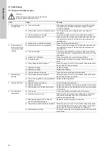
Page 22: ...ervice instructions for the pump e Pump stressed by the pipework Mount the pump so that it is not stressed Support the pipes See section 6 5 Pipe connection f Defective bearings Replace bearings g Defective coupling Replace the coupling h Foreign bodies in the pump Clean the pump and remove foreign bodies 3 Leaking pump housing a Pump stressed by the pipework Mount the pump so that it is not stres...

Page 23: ...pes 7 Oil pressure is too high or too low when engine is running a Oil filter blocked Replace the oil filter See installation and operating instructions for the diesel engine b Water or fuel in the oil Change oil See installation and operating instructions for the diesel engine c Oil level too low too high Refill with oil or drain off oil See installation and operating instructions for the diesel ...

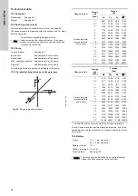
Page 24: ...TM06 2665 4514 FZ FX MX Fy My MZ Grey cast iron Flange size inch Forces N Fx Fy Fz ΣF Horizontal pump x axis parallel to pump shaft 2 890 2224 890 2555 2 5 1112 2780 1112 3194 3 1334 3336 1334 3832 4 1779 4448 1779 5110 5 2224 5560 2224 6388 6 2669 6672 2669 7666 8 3559 8896 3559 10221 10 4137 10364 4137 11901 12 4430 11103 4430 12749 14 4724 11841 4724 13596 16 5018 12580 5018 14444 18 5311 13318...

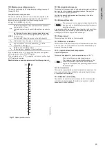
Page 25: ...y an arrow on the pump housing 15 11 Liquid and ambient temperature Liquid temperature The pump is designed for liquid temperatures up to 120 C Ambient temperature The maximum permissible ambient temperature depends on the driver and controller See installation and operating instructions for the driver and controller 15 12 Relative air humidity The relative air humidity must not exceed 80 Otherwis...

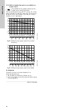
Page 26: ...nd altitude 16 Disposal This product or parts of it must be disposed of in an environmentally sound way 1 Use the public or private waste collection service 2 If this is not possible contact the nearest Grundfos company or service workshop Subject to alterations Note See installation and operating instructions for the engine for more detailed information TM03 4718 2606 TM03 4717 2606 20 25 30 35 4...

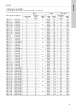
Page 27: ...NSI 5 750 149 1800 HSEF 6 17 JU6H UF52 8 6 ANSI 5 750 157 1760 HSEF 6 17 JU6H UF62 8 6 ANSI 5 766 179 1780 HSEF 6 17 JU6H UF30 8 6 313 ANSI 5 750 119 1760 HSEF 6 17 JU6H UF30 8 6 ANSI 5 750 118 1760 HSEF 6 17 JU6H UFABL0 8 6 ANSI 5 750 129 1760 HSEF 6 17 JU6H UF52 8 6 313 ANSI 5 750 157 1760 HSEF 6 17 JU6H UF62 8 6 ANSI 5 766 179 1780 HSEF 6 14Q JU6H UF50 8 6 277 ANSI 5 750 157 1760 HSEF 6 14Q JU6...

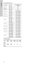
Page 28: ...rundfos JU6H UF52 Contact Grundfos JU6H UF62 Contact Grundfos HSEF 8 15A DP6H UFKA70 Contact Grundfos DQ6H UFKA50 Contact Grundfos DR8H UFKA40 Contact Grundfos HSEF 8 17W JU6H UFKAS0 Contact Grundfos DP6H UFKA50 Contact Grundfos DP6H UFKA70 Contact Grundfos HSEF 8 17Q DQ6H UFKA50 Contact Grundfos DQ6H UFKA60 Contact Grundfos HSEF 8 20G DQ6H UFKA60 Contact Grundfos DQ6H UFKA88 Contact Grundfos DQ6H...

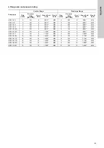
Page 29: ...6 125 8 9500 M20 5 125 8 8500 M20 HSEF 5 12 6 125 8 9500 M20 5 250 8 9250 M20 HSEF 5 14 6 125 8 9500 M20 5 125 8 8500 M20 HSEF 5 14N 6 125 8 9500 M20 5 125 8 8500 M20 HSEF 6 14Q 8 125 8 11750 M20 6 125 8 9500 M20 HSEF 6 17 8 125 8 11750 M20 6 250 8 10625 M20 HSEF 8 15A 10 125 12 14250 M24 8 125 8 11750 M20 HSEF 8 17Q 10 125 12 14250 M24 8 125 8 11750 M20 HSEF 8 17W 10 125 12 14250 M24 8 125 8 1175...

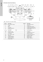
Page 30: ...r ring optional 37 Outboard bearing housing cover 13 Packing ring 40A In board deflector 14 14A Shaft sleeve RH LH 40B Out board deflector 14B Shaft sleeve O ring 46 Coupling key 16 In board ball bearing 47 In board bearing cover seal 17 Packing gland 63 Stuffing box bushing 17A Gland clip when used 73A Casing gasket nNot shown 17B Gland bolt 73B Bearing cover gasket 18 Outboard ball bearing 123 B...

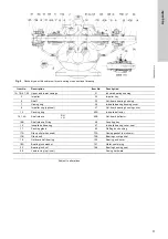
Page 31: ...er ring optional 37 Out board bearing housing cover 13 Packing ring 40A In board deflector 14 14A Shaft sleeve RH LH 40B Out board deflector 14B Shaft sleeve O ring 46 Coupling key 16 Inboard ball bearing 47 In board bearing cover seal 17 Packing gland 63 Stuffing box bushing 17A Gland clip when used 73A Casing gasket not shown 17B Gland bolt 73B Bearing cover gasket 18 Outboard ball bearing 123 B...

Page 32: ... tot en met 19 april 2016 De andere set is vanaf 20 april 2016 van kracht PL Deklaracja zgodności WE UE My Grundfos oświadczamy z pełną odpowiedzialnością że nasz produkt Fire HSEF system EN którego deklaracja niniejsza dotyczy jest zgodny z następującymi dyrektywami Rady w sprawie zbliżenia przepisów prawnych państw członkowskich Uwaga Poniżej podano dwa zestawy dyrektyw i norm Pierwszy zestaw ob...

Page 33: ...33 ...

Page 34: ...34 ...

Page 35: ...am dong Kangnam ku 135 916 Seoul Korea Phone 82 2 5317 600 Telefax 82 2 5633 725 Latvia SIA GRUNDFOS Pumps Latvia Deglava biznesa centrs Augusta Deglava ielā 60 LV 1035 Rīga Tālr 371 714 9640 7 149 641 Fakss 371 914 9646 Lithuania GRUNDFOS Pumps UAB Smolensko g 6 LT 03201 Vilnius Tel 370 52 395 430 Fax 370 52 395 431 Malaysia GRUNDFOS Pumps Sdn Bhd 7 Jalan Peguam U1 25 Glenmarie Industrial Park 40...

Page 36: ...69060 The name Grundfos the Grundfos logo and be think innovate are registered trademarks owned by Grundfos Holding A S or Grundfos A S Denmark All rights reserved worldwide Copyright Grundfos Holding A S www grundfos com ...

Reviews: