English (GB)
5
6. Electrical connection
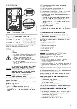
Fig. 1
Electrical connections, overview
The VFD is already connected to the DMX/DMH dosing pump,
only power supply must be connected.
6.1 Power supply
No special safety measures are required on the mains input side
of the frequency converter. It is advisable to use normal mains
fuses and a mains switch or circuit breaker.
Isolation from the connector to the mains must always be carried
out synchronously for all the poles (L1/L2/L2 or L1/N).
Connection cross section:
• 0.2 - 4/6 mm
2
rigid/flexible cable AWG 24-10
• For looping of the mains voltage, up to a cable cross section of
2 x 2.5 mm
2
double wire end sleeves must be used.
6.1.1 Connecting the VFD to the mains supply
1. Switch off the power supply.
2. Remove the front cover from the VFD power unit.
3. Pull the power supply cable through a cable gland.
4. Strip the cable covering to a length of approx. 3-5 cm and the
wires to a length of 7 mm.
5. Connect the wires to the power supply plug according to the
terminal diagrams printed in the VFD, see fig.
mains supply.
– 1-phase VFD variant: connect phase line (L1) to L1, neutral
line (N) to L2/N and protective earth (PE) to PE.
– 3-phase VFD variant: connect phase lines (L1, L2, L3) to L1,
L2/N and L3, and connect protective earth (PE) to PE.
– Tighten the screws with 0.5 - 0.6 Nm.
6. Tighten the cable gland.
7. Refit the front cover of the VFD power unit and tighten the
screws in the cover. Tighten the screws with 3.5 Nm ± 20 %.
7. VFD specification
7.1 VFD variants used with DMX and DMH pumps
The supplier offers a wide range of VFD variants. Grundfos DMX
and DMH pumps are available with selected VFD variants, as
follows:
• mounted on the pump motor
• IP66
• with integrated potentiometer
• without braking resistor (BW)
• not ATEX-approved.
7.2 Operation modes
The selection of the operation mode (manual or analog) can be
made by a central control unit.
• If AIN 1 (analog input 1) is activated, manual mode is selected,
and the VFD is operated via potentiometer.
• If AIN 2 (analog input 2) is activated, analog mode is selected,
and the VFD is operated via analog signal 4-20 mA.
7.2.1 Permanent setting of operation mode (VFD variant A)
If there is no central control unit, the operation mode can be set
permanently to manual or analog.
On default, the VFD is set to manual operation with integrated
potentiometer.
Manual operation with integrated potentiometer (default)
• 43 and 22 are connected with a jumper.
– Digital input 2 is activated.
– Analog input 1 "AIN 1", which is assigned to the
potentiometer, is activated.
• Speed control is only possible via the potentiometer.
For 4-20 mA analog control, the settings have to be made
according to chapter
Changing operation mode to analog control
Changing operation mode to analog control (optional)
See fig.
terminals.
• The jumper must connect 43 with 23. Disconnect jumper from
22 and connect it to 23.
– Digital input 3 is activated.
– Analog input 2 "AIN 2" is activated.
• Signal input is made via the terminals 40 (-) and 16 (+).
7.2.2 Operation modes for variants (VFD variants B - E)
T
M
06
46
06
28
15
VFD variant
Motor variant
Supply voltage
1~ (1-phase)
≤
0.75 kW
1~ (1-phase) 200-240 V
± 10 %, 47-63 Hz
3~ (3-phase)
> 0.75 kW
3~ (3-phase) 380-480 V
- 20 %/+ 10 %, 47-63 Hz
DANGER
Electric shock
•
Switch off the power supply before making any
connections.
•
The VFD cabinet must only be opened by
authorised and qualified staff.
•
All electrical connections must be carried out
by a qualified electrician in accordance with
local regulations.
•
Stripped parts of wires must not protrude from
terminals.
Caution
As soon as mains power supply is connected and
switched on, the pump can automatically start
operating depending on the potentiometer
setting. Make sure that the mains is only
switched on when the pump is ready for start-up
and operation, see installation and operating
instructions of the pump.
Caution
Observe the supplier manual "BU 0180" for the
VFD provided with the product.
10V 1
1
AIN1 14 AIN2 16 GND 40 24V 43 DIN1 21 DIN2 22 DIN3 23 DO1 1 GND 40 DO2 3 GND 40 SYS+77 SYS+78
L3 L2/N L1 PE
Mains supply
Terminals
Caution
Observe the supplier manual "BU 0180" for the
VFD provided with the product.
Note
For setting the operation mode for a VFD variant
B - E see thew supplier manual "BU 0180" for the
VFD.


