GRT Avionics HXr Installation Manual
Revision A5 A-12
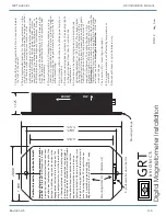
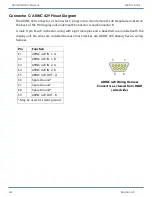
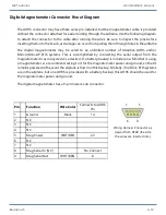
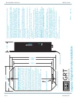
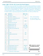
Digital Magnetometer Connector Pinout Diagram
The AHRS connector may have these wires pre-installed, but the magnetometer cable is provided
without the connector attached for easier routing through the airframe. Use the following diagram
to attach the connector to the cable after running the wires. Be sure to inspect the pins before
inserting them into the D-sub, as damage can occur from pulling them through holes in the airframe.
The digital magnetometer may be wired to an unlimited number of Adaptive AHRS and/or
Mini-X/Mini-AP EFIS systems. This is accomplished by connecting the serial output from the
magnetometer to as many devices a desired. If a battery-backup is included in a Mini that is using
a magnetometer, we recommend wiring to it for the magnetometer power and ground, so that it
remains powered in the event the airplane is flown on this backup. Similarly, if no Mini- EFIS systems
are in the airplane, but one AHRS is provided with a battery backup, this AHRS should be used for
the magnetometer power and ground.
The digital magnetometer has a 9-pin male d-sub connector.
Pin
Function
Wire Color
Connects to AHRS
Pin
1
Ground
Black
14
2
NC
3
NC
4
NC
5
Mag Power
WHT/RED
22
6
NC
7
NC
8
Mag Serial In (NC)
No Connect
9
Mag Serial Out
WHT/BRN
8
1
5
9
6
Wiring Harness Connector as
viewed from REAR (the side
the wires are inserted into).

