Revision A5 3-23
GRT Avionics HXr Installation Manual
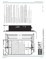
All magnetometer connections are made directly to the mating AHRS. This wiring includes the
power connections necessary for the magnetometer to operate. Each AHRS and magnetometer
pair is calibrated together for optimal accuracy, and thus this paring should be maintained.
3.5 Specific Equipment Interconnect Details
Detailed wiring information and setup instructions for specific GRT and third-party avionics
equipment are provided in Equipment Supplements. These supplements can be downloaded from
the GRT website in the Support section.
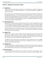
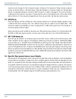
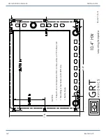
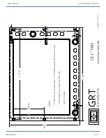
Examples of wiring diagrams and EFIS pinout diagrams can be found in the Appendix of this manual.
3.6 Autopilot Source Switch
Depending on the other equipment installed in the airplane, switches may be necessary or desirable
for some functions. A switch to allow the autopilot to be controlled by the EFIS, or directly from
the GPS, allows the GPS to control the autopilot in the event the display unit which normally
commands the autopilot is not functioning.
3.7 GPS Wiring from the Adaptive AHRS
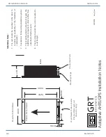
The GADAHRS can include an optional GPS receiver, or more accurately, a satellite navigation
receiver. This receiver can be configured to receive multiple constellations of navigation data, such
as the data from the US GPS system, the Russian Glonass, as well as Japanese and European systems
that are being developed.
The output from this GPS may be shared with all GRT EFIS display units as desired, as well as at
least two other devices, such as an ELT, transponder, etc. If these other devices impart too much
load on the serial output, the signal level will be reduced and some or all of these device will receive
no data.
An optional serial output from the display unit, to the GPS may also be made. If this connection is
not made, the GSNS will default to using all satellite constellations (not just the American GPS
system), and will be set to 1 position update per second. By making this connection, the satellites
used can be limited to the American GPS system only. We recommend allowing all satellite types,
and our EFIS is equally happy with once per second update rates as it is with five per second, so
the default settings are acceptable.
3.8 Inter-Display Communication
Display units communicate between themselves via Ethernet cable so that most entries made
during flight can be made from any display unit, and will be applied to all. The ethernet connection
is fast enough to transport large amounts of data, such as weather information, from one screen
to the other.
3.9 Audio Tone Output
Future growth is planned to allow audio output to provide a warning tone, or possibly other type
of audio output. This output may be connected to a spare input on the aircraft’s intercom system.

