background image

13

Revision date: 10.25.12

Assembly Instructions

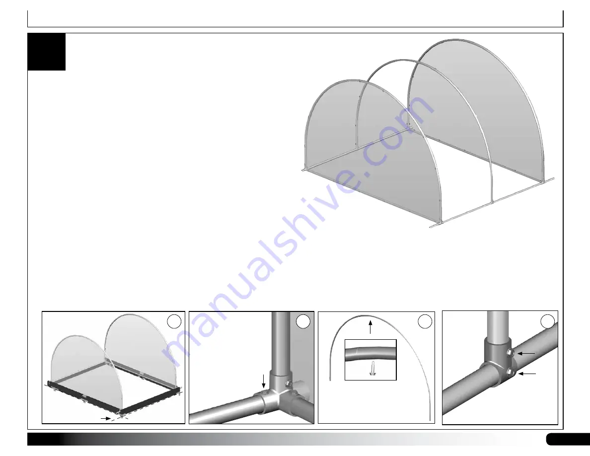
ASSEMBLE FRAME (continued)

5

7.  After all pipes are seated into the proper fittings and the slip tee fittings 

are in place and slide freely on the long pipes, carefully lift the cover 

frame and set it on the base frame (E).

8.  Adjust the frame as needed so that it fits the base. Use a light hammer 

to tap the frame fittings to adjust length if needed. 

Do not damage the 

fittings.

9.  After dry fitting the cover frame to the base frame, remove the cover 

frame from the base and install Tek screws to secure the pipes in the 

4-way fittings as shown below (F).  


NOTE:

 Do not over tighten the screws. Doing so may strip the threads 

in the hole cut by the self-tapping Tek screw. 

10. Locate the pipes needed for the mid rafter or rafters: #08R105P2 and 

#08R105S1. With the pipes properly seated, secure the rafter using 

FA4482 Tek screws (G). 

11.  Install the remaining rafter or rafters by inserting the rafter ends into the 

slip tee fittings on the long frame pipes.

12. Evenly space the middle rafter (or rafters for the 105146) between the 

two ends and 

secure the rafter to the fitting and the fitting to the frame 

pipe using Tek screws

 (H).


ATTENTION: 

Consult the All Frame Diagrams for additional information 

and dimensions.

When installing the Tek 

screws, it may be helpful 

to use a drill to start 

the screw and to keep 

it in place during the 

installation.

Drill bit should be 1/8"  

or smaller.

Ground Level

E

F

Tek 

screw

G

Tek screws are 

installed on the 

inside of cold 

frame.

H

Summary of Contents for Flip-Top Cold Frame

Page 1: ...owSpan All Rights Reserved Reproduction is prohibited without permission GrowSpan Flip Top Cold Frame Photo may show a different but similar model STK DIMENSIONS 105144 8 W x 5 H x 6 L 105145 8 W x 5...

Page 2: ...frame Please read these instructions before you begin If you have any questions during the assembly contact Customer Service at 1 800 245 9881 for assistance LOCATION Choosing the proper location is...

Page 3: ...ls consult the Quick Start Guide at the back of these instructions CARE AND MAINTENANCE Proper care and maintenance of your Flip Top Cold Frame will help to ensure reliable service The following items...

Page 4: ...104639 Pass Through Connector 105234 Slip Tee 104636 Corner Bracket 104642 A Angle Bracket 104645 Bracket Important Information PICTORIAL GUIDE The following graphics and photos will help you identify...

Page 5: ...section describes assembling your flip top cold frame The illustration below helps identify the main parts of the cold frame 1 Locate the required parts for each assembly procedure 2 Assemble base fr...

Page 6: ...ase and place the boards and the end frame members Steps 1 and 2 on a level surface for assembly CONSULT THE BASE FRAME DIAGRAM near the back of these instructions FOR PART LOCATION AND FRAME LENGTH D...

Page 7: ...ll board and the slot in the end board Center of the back board is aligned with the center of the slot 6 Attach the two 104642 A angle brackets to the assembled frame to reinforce the back board Use F...

Page 8: ...extensions of the corner brackets are driven into the ground to keep the frame square during the remainder of the assembly Longer frames include additional brackets to secure the joints of the long b...

Page 9: ...ntil both distances are equal 3 Once the distances are equal tap the corners down to set the frame in place NOTE Verify that the frame remains square as you complete Step 3 The site must be level for...

Page 10: ...approximately 94 long 105P094375 4 Insert the fittings onto the ends of the pipe as shown until they are seated tightly in place Verify that the base of the end rafter aligns with the base frame A Ad...

Page 11: ...to trace around the rafter to mark the outline of the end wall and draw a vertical line to the edge of the panel material See arrows in Diagram A 3 After marking the material cut the end panel from t...

Page 12: ...mble the top of the cold frame B Verify that the straight pipe is seated into each 4 way fitting 4 Move to one 1 4 way fitting at one end rafter and insert the short 2 section of pipe used as a hinge...

Page 13: ...rip the threads in the hole cut by the self tapping Tek screw 10 Locate the pipes needed for the mid rafter or rafters 08R105P2 and 08R105S1 With the pipes properly seated secure the rafter using FA44...

Page 14: ...t if needed The 105146 cold frame has an H channel splice between the end rafters where sections of the PolyCor cover meet See the Cover Frame diagram Helpful Hints The edges of the main cover are tri...

Page 15: ...ntinue with these steps 1 With adequate assistance lift and set the assembled frame onto the recycled plastic lumber base The short hinge pipes are set into the slots of the base end boards 2 Locate o...

Page 16: ...ame and use the pipes to keep the top open as shown in the photo to the right 6 Locate the black nylon straps Loop one strap around the end rafter pipe and attach it to the inside of the pipe using a...

Page 17: ...ate 10 25 12 105146 DIMENSIONS 8 W x 5 H x 12 L QUICK START GUIDE 8 Wide Flip Top Cold Frame Quick Start Guide DIMENSIONS 8 W x 5 H x 6 L 105144 105145 DIMENSIONS 8 W x 5 H x 8 L Actual dimension may...

Page 18: ...ers The frame is positioned upside down for assembly It is flipped when set on the site shown above The long boards of the frame are positioned between the pre slotted end boards Install brackets towa...

Page 19: ...itioned between the pre slotted end boards DIMENSIONS 8 W x 5 H x 8 L Length of the Front and Back Base Frame Boards is 96 NOTE Dimension shown is between the end frame members Install brackets toward...

Page 20: ...s Install brackets toward the inside of the brackets that secure the back board of the base frame as shown DIMENSIONS 8 W x 5 H x 12 L Length of the Front and Back Base Frame Boards is 146 1 8 NOTE Di...

Page 21: ...Spacing 5 11 on center Rafters Frame Only 6 5 1 8 outside Baseboard Frame Side Profile 105144 105145 105145 105144 3 11 1 2 on center Rafter Spacing 7 11 on center Rafters Frame Only 8 5 1 8 outside...

Page 22: ...22 Revision date 10 25 12 Side Profile 105146 3 11 1 2 on center Rafter Spacing 11 10 1 2 on center Rafters Frame Only 12 5 1 8 outside Baseboard Frame 105146 Actual dimension may vary slightly...

Page 23: ...H channel the 105142 cold frame includes a center section of H channel The section of H channel connects the two separate pieces of PolyCor during the installation With the two sections of PolyCor cut...

Reviews: