4
English
Application
Operation is possible in conjunction with:
• Pressurized storage heaters
Operation is
not
possible with:
• Low-pressure storage heaters (displacement water heaters)
Specifications
• Max. flow
8.3 L/min or 2.2 gpm/60 psi
GROHE WaterCare
5.7 L/min or 1.5 gpm/60 psi
• Flow pressure
- min.
7.25 psi
- recommended
14.5 - 72.5 psi
- greater than 72.5 psi, fit pressure reducing valve
• Max. operating pressure
145 psi
• Test pressure
232 psi
• Temperature
- max. (hot water inlet)
176
°
F
• Water connection
cold on right side
hot on left side
Note:
Major pressure differences between cold and hot water supply
should be avoided.
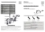
Installation
Refer to the dimensional drawing on fold-out page I.
Flush piping system prior and after installation of faucet
thoroughly!
Side valves,
see figs. [1] and [2].
• Valve with a groove on the top edge of the cartridge (A) and
in addition marked with blue tape should be mounted on the
right (cold water) side.
• Valve without a groove on the top edge of the cartridge (A)
and in addition marked with red tape should be mounted on
the left (hot water) side.
1. Screw the mounting set (B) to the bottom of the thread of the
side valve (C).
Make sure that the rubber washer (B1) is on the top of the
fiber washer (B2).
2. Insert the side valve (C) through the basin hole from below.
3. Slide on seals (D) and screw on nut (E).
Make sure that the fiber washer (D1) is on the top of the
rubber washer (D2).
4. With 32mm open-ended spanner fasten the side valve (C).
The distance between the top of the headpart and the basin
must be 1 25/32", see fig. [2].
5. Screw the escutcheon (F) down to the nut (E), see fig. [1].
Install lever (18 077)
not included in the scope of delivery,
see fig. [3].
- Push ring (G) onto headpart (A).
- Push on lever.
- Tighten with screw (H) and insert cap (I).
Install lever (18 085)
not included in the scope of delivery.
- Push on lever complete and screw cap (J) onto
headpart (A).
Fit spout,
see fig [4].
Mount lift rod,
see fig. [5].
Insert the lift rod (K) through the spout and screw on the lower
lift rod (L).
The connector is at the lower lift rod (L).
Fit pop-up drain (28 957),
see fold-out page I, ensure that
flange of pop-up drain is sealed.
Connect wideset,
see figs. [5] and [6].
Connect the side valves to the water supply. Ensure the
supplied washers are used for all connections.
The cold water supply should be connected on the right side
valve (marked blue) and the hot water supply to the left valve
(marked red).
Open cold and hot water supply and check connections
for leakage!
Maintenance
Inspect and clean all parts, replace as necessary and grease
with special grease.
Shut off cold and hot water supply!
I. Replacing the headpart,
see fig. [7].
1. Remove lever (18 077):
- Detach cover cap (I) and screw out screw (H).
- Pull off lever.
- Pull off ring (G).
Lever (18 085):
- Unscrew cap (J) and pull off lever complete.
2. Unscrew headpart (A) using a 17mm socket wrench.
3. Change complete headpart (A) or O-ring (A1).
Observe the different replacement part numbers of the
headparts,
see fold-out page I.
II. Unscrew and clean flow regulator (13 955),
see fold-out
page I.
Assemble in reverse order.
Replacement parts,
see fold-out page I ( * = special
accessories).
Care
Instructions for care of this faucet will be found in the Limited
Warranty supplement.