5
OM-BPM-15/30/40G(C,A) (CE) INTERNATIONAL
2. Put enough water into the pan to cover the bottom to a depth of 1/4 to 1/2 inch
(6 to 13 mm). With the pan body in the horizontal position, note how the water
lies in the pan, to confirm that the pan was leveled properly during installation.
3. Verify that the rear heat shield is in place.
4. Following “To Start Pan” instructions for your pan model, begin heating the
water at a temperature setting of 235°F (113°C). At this setting, heating should
continue until the water boils.
5. To shut down the unit, switch the power switch to “OFF”.
6. Turn the tilting handwheel clockwise to pour out the water and to confirm that
the pan body can be tilted smoothly from horizontal to vertical. For power tilt
models, push the UP/DOWN switch to confirm operation of tilting system.
If the unit functions as described above, it is ready for use. If it does not, contact
your local Engineer (CE).
SETTING THE GAS PRESSURE
1. During commissioning, a gas pressure check is essential. Connect a suitable
pressure gauge to the gas manifold to perform this test. The pressure gauge
should be connected to the test nipple. See photograph above, left.
2. Turn the gas and electricity mains on.
3. Light the burners as described above.
4. Manifold gas pressure should be as noted in the Installation section of this
manual. If adjustment is necessary, follow steps 5 through 10, below.
5. Remove the screws which secure the ignition module cover and remove the
ignition module cover panel. See image above, center.
6. Remove the governor cap screw on the gas control valve to gain access to the
screw inside the turret. See image above, right.
7. The governor is suitable for both natural and propane gas.
8. Turn the screw inside the turret clockwise to increase the pressure, anti-
clockwise to reduce it. Check the burner pressure again after 15 minutes
operation, and adjust if necessary.
9. Disconnect the pressure gauge from the test point. Reseal the test point and
test for gas soundness.
10. Replace governor cap screw, and replace control box panel and lid.
INSTALLER
DANGER: FLAMMABLE
WARNING: DO NOT OVERFILL WITH OIL OR FIRE MAY RESULT!
CAUTION: THE TEMPERATURE MUST NOT EXCEED 200ºC OR THE HIGH LIMIT
THERMOSTAT WILL TRIP.
IMPORTANT: THESE APPLIANCES MUST BE INSTALLED BY A COMPETENT PERSON IN
CONFORMITY WITH THE INSTALLATION AND SERVICING INSTRUCTIONS
AND NATIONAL REGULATIONS IN FORCE AT THE TIME. PARTICULAR
ATTENTION MUST BE PAID TO THE FOLLOWING:
I. E. E. REGULATIONS FOR ELECTRICAL INSTALLATIONS
ELECTRICITY AT WORK REGULATIONS
GAS SAFETY (INSTALLATION & USE REGULATIONS
HEALTH AND SAFETY AT WORK ACT
FIRE PRECAUTIONS ACT
LOCAL AND NATIONAL BUILDING REGULATIONS
DETAILED RECOMMENDATIONS ARE CONTAINED IN INSTITUTE OF GAS
ENGINEERS PUBLISHED DOCUMENTS: IGE/UP/1, IGE/UP/2, BS6173 AND
BS5440.
After installing and commissioning the appliance, the User’s Instructions should be
handed to the user or purchaser. Ensure that the instructions for lighting, turning
off, correct use and cleaning are properly understood. Emphasize the location of the
main gas isolating valve and demonstrate the emergency shut down procedure.
OPERATION
CAUTION: DO NOT HEAT AN EMPTY PAN FOR MORE THAN FIVE MINUTES AT A SETTING
HIGHER THAN 300°F (149°C). DAMAGE TO THE PAN COULD RESULT.
WARNING: KEEP THE AREA AROUND BRAISING PAN FREE AND CLEAR OF COMBUSTIBLE
MATERIALS.
CAUTION: KEEP FLOORS IN BRAISING PAN WORK AREA CLEAN AND DRY. IF SPILLS
OCCUR, CLEAN IMMEDIATELY TO AVOID THE DANGER OF SLIPS OR FALLS.
CAUTION: REPLACE THE HOLE PLUG BEFORE CLEANING OTHERWISE WATER COULD
ENTER THE ELECTRICAL CONTROL BOX AND DAMAGE THE PARTS.
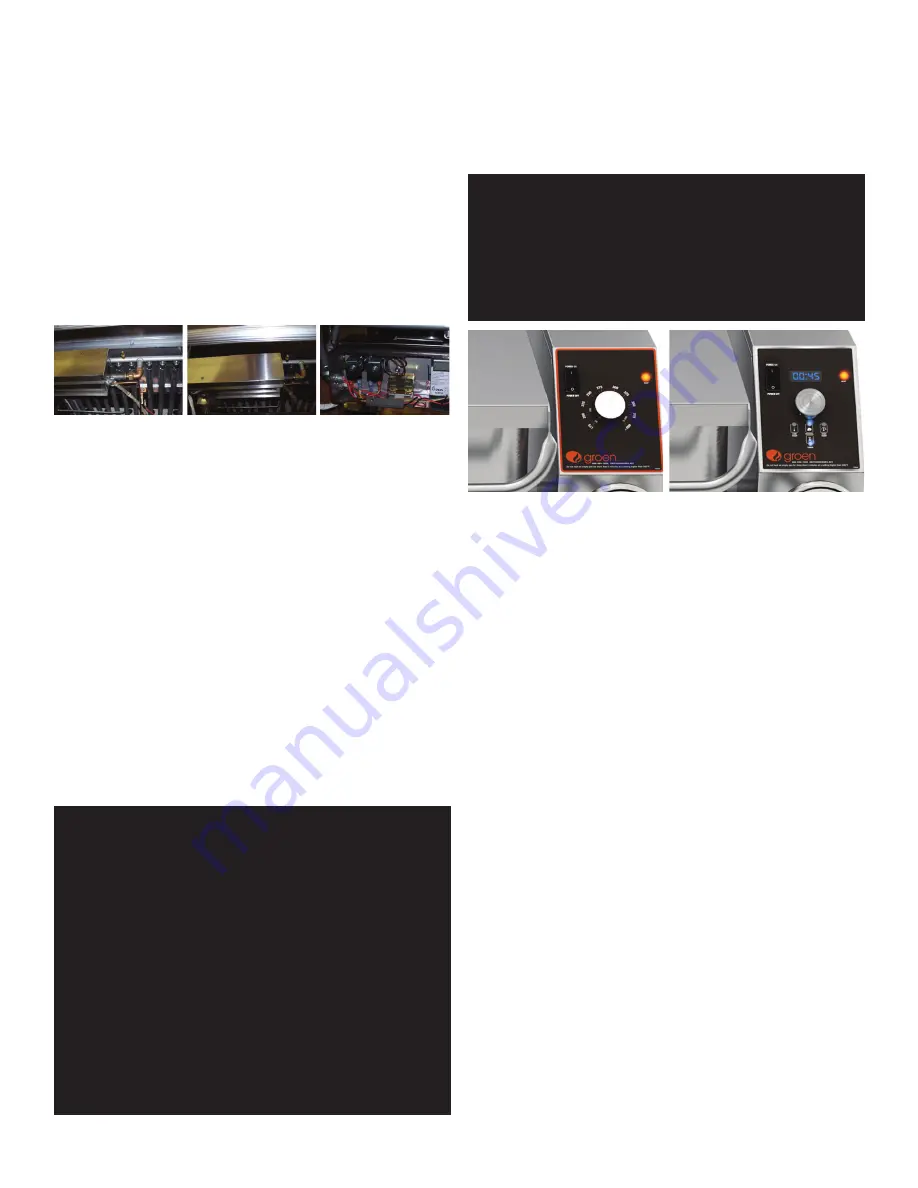
Classic Control
Advanced Control
OPERATOR CONTROLS
1. Classic Control (-GC) Models
a. Lighted Power ON switch located on the control console. It controls main
power to the unit.
b. The temperature knob, located on the control console, is used to set the
pan temperatures between 175° and 425°F (79° and 218°C).
c. Heating indicator light is located on the control console, it illuminates
when the controller calls for the main gas valve to open. If the unit is tilted,
the call for heat will be interrupted and the light will turn off until the unit
is returned to the cooking position.
d. A handwheel controls the worm and gear mechanism that smoothly tilts
the pan body and holds it in the desired position
2. Advanced Control (-GA) models
a. Lighted Power ON switch located on the control console. It controls main
power to the unit.
b. Heating indicator light is located on the control console, it illuminates
when the controller calls for the main gas valve to open. If the unit is tilted,
the call for heat will be interrupted and the light will turn off until the unit
is returned to the cooking position.
c. SET TnnP Mode – Allows the pilot to light but the main burners remain off;
unit will go into SET TnnP mode at start-up automatically and remain there
until the user uses one of the LOW TEMP, MANUAL or HIGH TEMP buttons
to specify the set temperature.
d. LOW TEMP Button – Used to set operating temperature on of the pan at
a preset low temperature (default = 175°F/79°C). Can be pressed at any
point during operation of the unit to change the set temperature to the
preset value except when there is an active TIMER enabled.
e. MANUAL button – Enables the user modify the desired cooking
temperature of the pan (between 175°F/79°C and 425°F/218°C) using
the temperature knob and display (default = 212°F/100°C). The operator
will press the MANUAL button and set the desired temperature using the
temperature knob and display. Once the desired temperature is shown in
the display, the user may either press the MANUAL button again or wait
5 seconds and the set temperature will be accepted by the control and
locked in. After the set temperature is accepted, it may be changed at any


